AE TECHRON MULTI-AMP CONFIGURATION GUIDE
6
Information subject to change
97-8002465_09-19-14
2
Multi-amp System Principles
The following configuration and operating principles apply to 2100 or 7000-Series multi-amp systems.
Following these basic principles will help to ensure the safety of your equipment and personnel.
2.1
One Master Amplifier for Series Systems
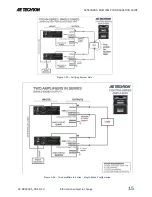
Series multi-amp systems are configured with one amplifier configured as the
Master
amplifier, and all other
amplifiers in the system configured as
Slave
amplifiers. DO NOT operate with more than one Master in your
Series multi-amp system.
2.2
All Master Amplifiers for Parallel Systems
Parallel multi-amp systems are configured with all amplifiers configured as
Master
amplifiers. To avoid
problems that might occur with signal latency, the input signal is sent through a parallel input cable that
delivers the signal simultaneously to all amplifiers in the system.
2.3
Use only 2100 or 7000-Series Amplifiers of the same Model Number
Use only AE Techron 2100 or 7000-Series amplifiers of the same model to construct these multiple amplifier
systems. You CANNOT combine different models of 2100 or 7000-Series amplifiers in the same system,
such as combining 7224 amplifiers with 7548 amplifiers. All amplifiers must be in good working order. Never
use other model AE Techron amplifiers or amplifiers made by another manufacturer in a 2100/7000-Series
multi-amp system. Such improper connections could damage the amplifiers.
2.4
Use Correct Wiring
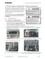
Never directly connect one amplifier’s
OUTPUT
terminal (on the output terminal block) to another amplifier’s
OUTPUT
terminal. The resulting circulating currents will waste power and may damage the amplifiers.
Depending on the configuration to be used, the
OUTPUT
terminal of one amplifier should only be directly
connected to the next amplifier’s
COM or SAMPLED COMMON
terminal, to the
load
, or to a
ballast resistor.
2.5
When Constructing Output Wiring, Use These Basic Criteria
In multi-amplifier systems, the quality, gauge, length and rating of the output wiring leading to the load can
affect system performance.
Wire gauge
refers to the diameter of solid wire and is an important factor in the
wire’s current-carrying capacity. For Parallel system output wiring, we recommend a wire gauge from 4 AWG
(2120/7796 systems) to 10 AWG (2105/7224 systems), and a length of 2.5 to 4 feet. Refer to the Wire
Current-Carrying Capacity chart in
Appendix A
for more information.
Wire length
is also an important factor. Particularly in Parallel multi-amp systems, the output wire branches
to each amplifier must be carefully matched in length to within ¼-inch to ensure system operation. To assist
with output wiring requirements in Parallel systems, AE Techron offers
Parallel System Wiring Kits
that
contain pre-built output wiring. See
Section 1.3
for a description of these and other multi-amp accessories.
See
Appendix B
for more information on critical wire lengths in a Parallel system.
Wire rating
refers to the allowable voltage handled by the wire. In configuring Series systems for increased
voltage, make sure that the wire insulation on output wiring is appropriate for the expected output voltage.
Wire length should also be limited to 3 to 4 feet to minimize voltage drop.
2.6
Operate with Safety in Mind
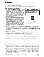
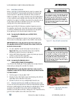
Potentially lethal voltages and currents are present within the 2100/7000-Series amplifiers. While the
amplifiers’ chassis are earth grounded, all internal grounds are floating. Particularly in systems assembled
for increased voltage (Series configurations), all internal grounds of Slave amplifiers could carry lethal
voltage levels.


