Information subject to change
96-8006123_11-03-2021
8302 OPERATOR’S MANUAL – SECTION 4
10
4
Amplifier Operation
4.1
Front-Panel Controls and Indicators
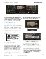
This section provides an overview of Front-Panel
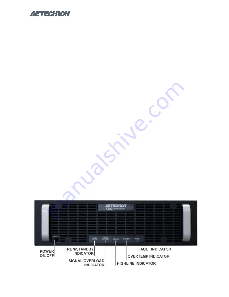
controls and indicators found on the 8302. Refer fo
Figure 4.1
for component locations.
4.1.1 Power Switch
The Power switch controls the power to the ampli
-
fier’s high-voltage transformers.
Switch to the ON
position (right) to energize the amplifier. Switch
to the OFF position (left) to remove power from
the high-voltage transformers and place the
amplifier in Standby mode.
4.1.2 Run/Standby Indicator
Run mode:
The indicator will be lit solid green.
The amplifier’s high-voltage transformers are ener
-
gized and the unit will amplify the input signal.
Standby mode:
The indicator will be lit solid am
-
ber. The amplifier will be placed in Standby when
one of the following conditions occurs:
1.
High/Low Line error
2.
Overtemp condition
3. Fault condition
4.
The user sets the front-panel Power switch to
the OFF (left) position.
In Standby mode, the amplifier’s low-voltage trans
-
former is energized but the high-voltage transform
-
ers are not.
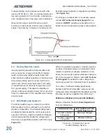
Figure 4.1 – Front Panel Controls and Indicators
To release the amplifier from Standby mode:
1.
High/Low Line error:
Clear the over- or un-
der-voltage condition. The amplifier will resume
operation when the input voltage is brought
within the operating range of the amplifier.
2.
Overtemp condition:
Remove the input signal
from the amplifier and leave the amplifier with
the Power switch in the ON position and with
the fans operating to cool the amplifier. When
the amplifier’s internal temperature drops to
less than 100°C, the amplifier will resume
operation.
3.
Fault condition:
Turn the front-panel Power
switch to OFF and then back to ON to reset the
amplifier. If the fault condition recurrs or does
not clear, the amplifier may require servicing.
See the
Troubleshooting
section for more
information.
4.
Power switch pressed:
When the amplifier is
operating (Run mode), setting the front-panel
Power switch to the OFF position (left) will
place the amplifier in Standby mode. Set the
switch to ON (right) to release the amplifier
from Standby and return the amplifier to Run
mode.
4.1.3 Signal/Overload Indicator
Signal Presence:
When an input signal is pre
-
sented at an active signal input on the amplifier
at a lever greater than 0.5V, the Signal/Overload
indicator will light solid green.
Summary of Contents for 8302
Page 2: ......


