Information subject to change
96-8006123_11-03-2021
8302 OPERATOR’S MANUAL – SECTION 5
14
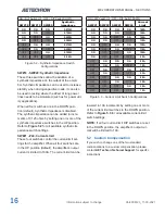
5.1
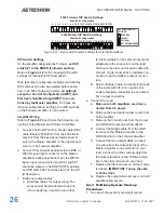
DIP Switch Configurations
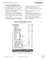
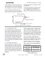
The 8302 amplifier provides 24 DIP switches locat
-
ed on the amplifier back panel. Most configuration
settings can be made using these DIP switches.
See
Figure 5.1
for default DIP switch settings and
descriptions.
SW#1: Unbalanced Input
When this switch is in the UP position (default), the
unabalanced BNC input connector is enabled and
can be used to send an input signal to the ampli
-
fier. When this switch is in the DOWN position,
this connector is disabled. Note that disabling an
unused input connector can help to minimize noise
going into the amplifier.
SW#2: Balanced Input
When this switch is in the UP position, the bal
-
anced WECO input connector is enabled and
can be used to send an input signal to the ampli
-
fier. When this switch is in the DOWN position
(default), this connector is disabled. Note that
disabling an unused input connector can help to
minimize noise going into the amplifier.
SW#3: DC Servo
The DC Servo function ensures that no DC offset
is present at the signal output (-3 dB at 3 Hz).
Se-
lect DC Servo when driving transformers or other
coils. When the DC Servo DIP switch is in the UP
position, the DC Servo function is enabled. When
this switch is in the DOWN position (default), the
DC Servo function is disabled.
signal. When this switch is in the DOWN position,
the amplifier will operate in Controlled-Current
mode, and the amplifier’s output current will be
controlled by its input voltage signal.
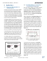
IMPORTANT:
Controlled-Current operation re
-
quires the use of a compensation network. The
8302 amplifier provides two installed compensa
-
tion networks: one suitable for loads from 50
μ
H to
500
μ
H; the other suitable for loads from 500
μ
H to
1.5 mH. For more information on Controlled-Cur
-
rent operation, including instructions for selecting
the best compensation option for your application,
see the topic “Controlled Current Operation” in
the Applications section of this manual. If neither
of the available RC networks is suitable for your
application, please contact
AE Techron Technical
Support.
SW#5: Compensation Network 2
When the 8302 amplifier is used in Controlled-
Current mode, the current control loop is tuned
with an RC network. The factory default network
(Compensation Network 1) provides 100k ohm
resistance and 2.2 nF capacitance and should be
used with loads that are 50 µH to 500 µH. If this
default network is not adequate for your application
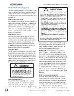
In Controlled-Current Mode, the load is part of the amplifier
circuit, and the relationship of the load to the amplifier is
critical. For proper and safe operation in Controlled-Current
mode, you must obverve the following guidelines:
1.
Properly attach a load before operating the amplifier.
2.
DO NOT use a blocking capacitor.
The load must have
a DC path.
3.
Never leave the load open.
If you feel the load must be
fused, which could lead to a potential open circuit, please
contact AE Techron Technical Support.
4.
Check to make sure the load has some inductive
component.
5.
Provide appropriate Compensation for the load, using
either Compensation Network 1 (SW#6) or Compensa-
tion Network 2 (SW#5).
If neither compensation network
is adequate for your load, contact
AE Techron Technical
Support.
6.
Turn off the amplifier immediately if oscillation oc-
curs.
Failure to follow these guidelines may result
in damage to the amplifier or load.
CAUTION
Do not change the setting of the Operation
Mode switch while the amplifier is operat-
ing (Run mode). Damage to the amplifier or
the load can occur. Place the amplifier in
Standby mode by pressing the front-panel
Power switch OFF before changing the
Operation Mode setting.
CAUTION
SW#4: Operation Mode
When the Operation Mode DIP switch is in the
UP position (default), the amplifier will operate
in Controlled-Voltage mode, and the amplifier’s
output voltage will be controlled by its input voltage
Summary of Contents for 8302
Page 2: ......


