96-8006123_11-03-2021
Information subject to change
19
8302 OPERATOR’S MANUAL – SECTION 6
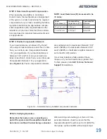
STEP 2: Determine Required Compensation.
When operating an amplifier in Controlled-
Current mode, the load becomes an integral part
of the system. In order to determine the required
compensation for your load, consulting the follow
-
ing table to determine the approximate compen
-
sation capacitance (CC) required based on the
inductance of your load. Note that these calcula-
tions are based on empirical measurements and
are approximate.
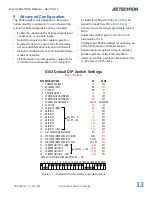
If your load inductance is between 75
μ
H and 1
mH, and your load resistance is less than 5 ohms,
then you can likely use Compensation Network
1 for your application. If your load inductance is
between 1 mH and 5 mH, and your load resis
-
tance is less than 5 ohms, then you can likely use
Compensation Network 2 for your application.
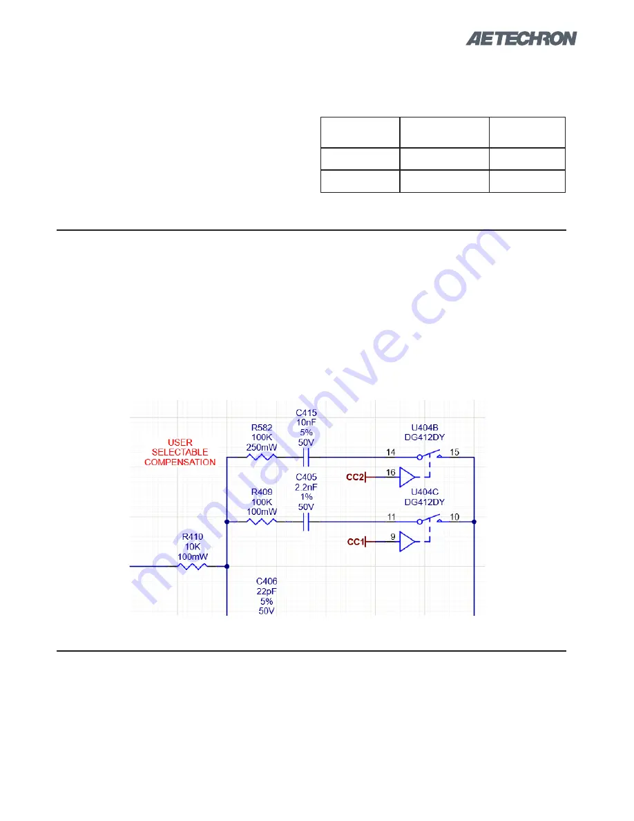
(See
Figure 6.4
). These compensation networks
NOTE: Load Resistance (R) is assumed to be
<5 ohms.
STEP 3: Enable Compensation Network
are enabled when Compensation Network 1 DIP
switch (SW#6) or Compensatlon Network 2 DIP
switch (SW#5) on the Master amplifier module is
set to the ON (UP) position.
If your load inductance falls outside of these
ranges, or if your load resistance is greater than
5 ohms, please contact
AE Techron Technical
Support
for assistance.
STEP 4: Verifying Operation
Remember the load you are connecting is a
part of the system and the amplifier should not
be turned on without the load being connected.
After selecting and enabling your choice of Com
-
pensation Network, check to ensure that the
Operation Mode DIP switch is set to CC (DOWN),
then power up the amplifier without signal input.
Load
Inductance (L)
Compensation
Capacitance (CC)
Compensation
Network
75 µH to 1 mH
0.0022 µF
Network 1
1 mH to 5 mH
0.0100 µF
Network 2
Figure 6.4 – Selectable factory-installed compensation networks
Summary of Contents for 8302
Page 2: ......

