96-8006123_11-03-2021
Information subject to change
7
8302 OPERATOR’S MANUAL – SECTION 3
are operating correctly. Once proper operation is
confirmed, refer to the
Applications
section of this
manual for instructions on configuring and operat
-
ing your amplifier in Controlled-Current mode.
3.1 Connecting the Load
3.1.1
Preparation and Cautions
Before connecting the amplifier, make sure the
AC power is disconnected.
Always use the appropriate wire size and insula
-
tion for the maximum current and voltage expected
at the output. Never connect the output of the
amplifier to any other model amplifier, power sup
-
ply, signal source, or other inappropriate load; fire
can result.
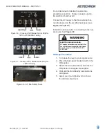
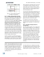
Be sure to install the output safety cover after wir
-
ing the output connections. See
Figure 3.3.
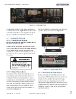
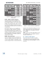
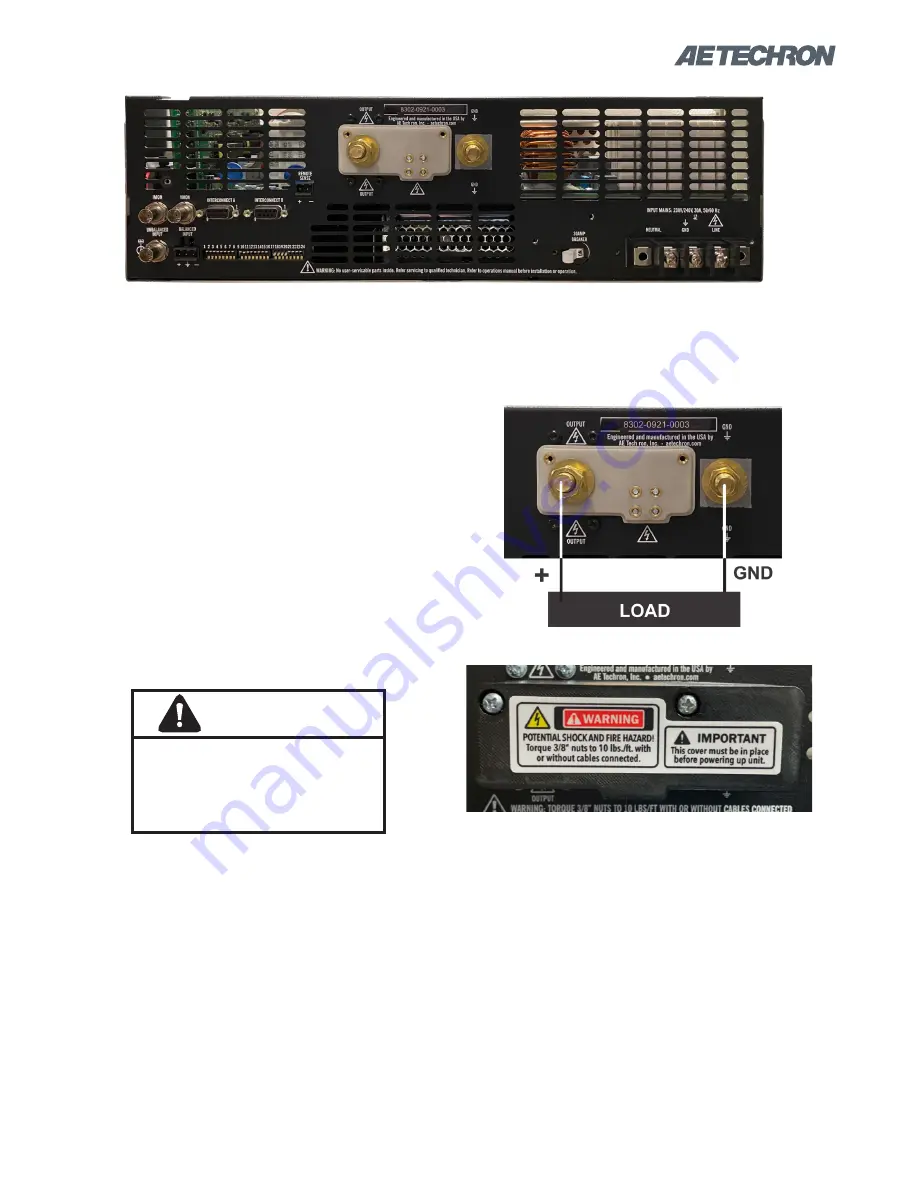
Figure 3.1 – 8302 Back Panel
ELECTRIC SHOCK HAZARD.
Output potentials can be lethal. Output
cover must remain installed at all times
to protect against HAZARDOUS LIVE
VOLTAGES
WARNING
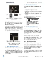
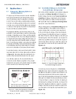
Figure 3.2 – Connecting the Load
Figure 3.3 – Outputs Safety Cover
3.1.2 Output Connections
Connection to the output of the amplifier is to a
pair of high-current output terminals. Wires ter
-
minated with 3/8-inch ring terminals are recom
-
mended when connecting to the output terminals.
Connect the load across the terminals marked
“OUTPUT” (positive) and “GND” (ground). The
GND terminal also can be connected to an ex
-
ternal ground point such as the rack chassis, if
desired. See
Figure 3.2.
3.2 Connecting the Input Signal
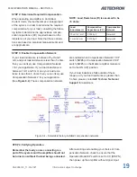
Both an unbalanced Input BNC jack and a bal
-
anced Input “WECO” terminal block connector are
provided on the amplifier back panel for signal
input. Connect your input signal source to the
unbalanced or balanced input connector as shown
in
Figure 3.4.
Use cables that are high quality and
shielded to minimize noise and to guard against
possible feedback.
Summary of Contents for 8302
Page 2: ......


