

11
Section 2 Setup and Basic Operation
General Information
The following pages provide some basic information concerning cable
construction and how a step TDR works. This information is designed to help
users set up their TDRs and better understand what a step TDR can show about
a particular cable type. The information in Section 2 is for basic operation. Full
cable parameters, testing explanations, test and measurement setups, and
example traces are covered in Section 3.
Step TDR Operation
TDR’s are divided into two basic types: Pulse and Step. A pulse TDR sends out
just one pulse at a time and waits until no more reflection can be received from
that pulse to send another pulse. This requires adjusting the pulse width and/or
gain control on those TDR’s to clearly see longer cables and faults further away.
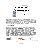
Step TDR’s, like the E20/20 TDR and Avionics TDR, transmit continuous wave
sweeps on the cable and interpret the reflections to provide more detailed
information on the condition of the cable. A Step TDR can not only provide
accurate distance to the end of the cable or faults. It can also provide the cable’s
impedance over length, loop resistance and more detailed reflective information
to determine fault type and amplitude.


