13
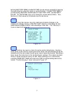
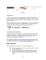
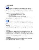
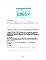
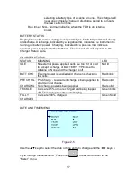
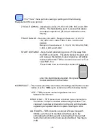
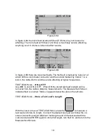
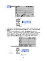
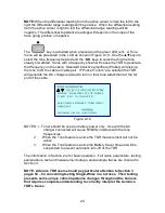
Figure 2-3
Velocity Factor
A cable’s velocity factor (VF) is also designed in at the time of manufacture. VF
is expressed as a fraction of the speed of light in a vacuum [c]. A VF of 0.677c
indicates that a transmitted wave travels along that cable at 67.7% the speed of
light in a vacuum.
TDR’s measure the delay time of the reflected signals. The time is divided in two
because it is always a round trip, then multiplied by the cable’s VF in feet or
meters per second to obtain the distance to a particular reflection.
Loop Resistance and dribble up
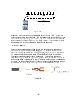
Along with measuring the impedance of a cable, a Step TDR also measures a
cable’s loop resistance. The result is a slight upward slope over distance of the
cable as the loop resistance is added to the impedance reading. This
phenomenon is referred to as “Dribble Up.”
More detailed information about impedance, velocity factor and loop resistance
are contained in Section 3 in this manual, AEA Technology’s TDR application
notes found on the enclosed CD, and at
www.aeatechnology.com
.
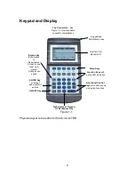
Menu Navigation
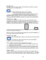
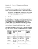
When working in the menus here are some basic navigation rules:
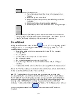
▼▲
Use the up/down arrow keys to move the menu cursor [
] to the
desired feature/function.
◄►
Use the right arrow key to enter a feature or function and make
selections. Many features have a hidden horizontal menu of
options. Use the left/right arrows to reveal and select the option
desired.
Time
2
X Velocity = Distance

