
18
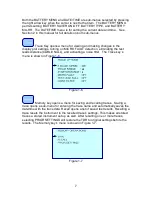
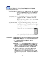
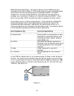
The “Trace” menu permits viewing or setting all of the following
Measurement Screen options:
Z SCALE (OHMS) – Impedance scales: 20, 50, 100, 200, 500, and 1,000
Ohms. The best starting point is a scale that places
the cable’s impedance (Z
0
) about mid-scale on the
display.
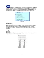
TRACE RANGE – Sets the plot width. Ranges in feet are: 10, 20, 50,
100, 200, 500, 1,000, 2,000, 5,000, 10,000, and
20,000.
Ranges in meters are: 2, 5, 10, 20, 50, 100, 200, 500,
1,000, 2,000, and 5,000.
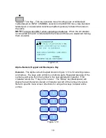
START DISTANCE – Sets the left plot starting point xx ft (m) away from
the TDR’s connector. The plot will show the start and
end range at the bottom. Cursor distances will still be
measured from the TDR’s connector or end of a “Test
Lead Null” if on.
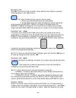
Press the
►
then use the alpha-numeric keypad to
enter the start distance desired, then press
to save and return to the menu.
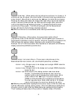
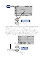
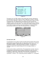
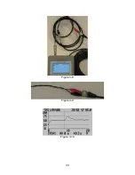
MICROFAULT – This feature provides two modes of locating small faults on coax
cables. Use the
◄►
keys to select one of the following modes:
OFF – TDR presents normal impedance trace on
Measurement Screen.
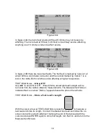
KINKS ONLY – TDR presents an amplified trace of reflections
from kinks, crimps or crushed areas along the cable. The
cable’s Z
0
is plotted at the bottom of the plot with the faults
appearing as upward refection spikes. See figure 2-6A.
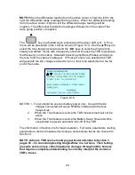
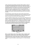
ALL FAULTS – TDR presents a reduced Z Scale trace with
dribble up removed to maintain a flat trace at Z
0
. By
eliminating the dribble up and reducing the Z Scale small
faults of any kind can be more easily identified. See figure
2-6B