24
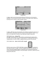
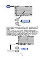
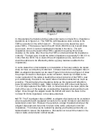
NOTE: When the differential reading from the active cursor is from the left to the
right the differential range readings will be positive. When the differential reading
from the active cursor is right to left the differential range readings will be
negative. The differential impedance readings will depend on the slope of the
trace going positive or negative.
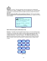
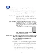
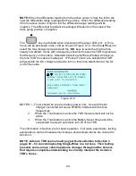
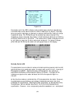
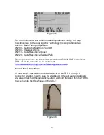
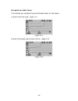
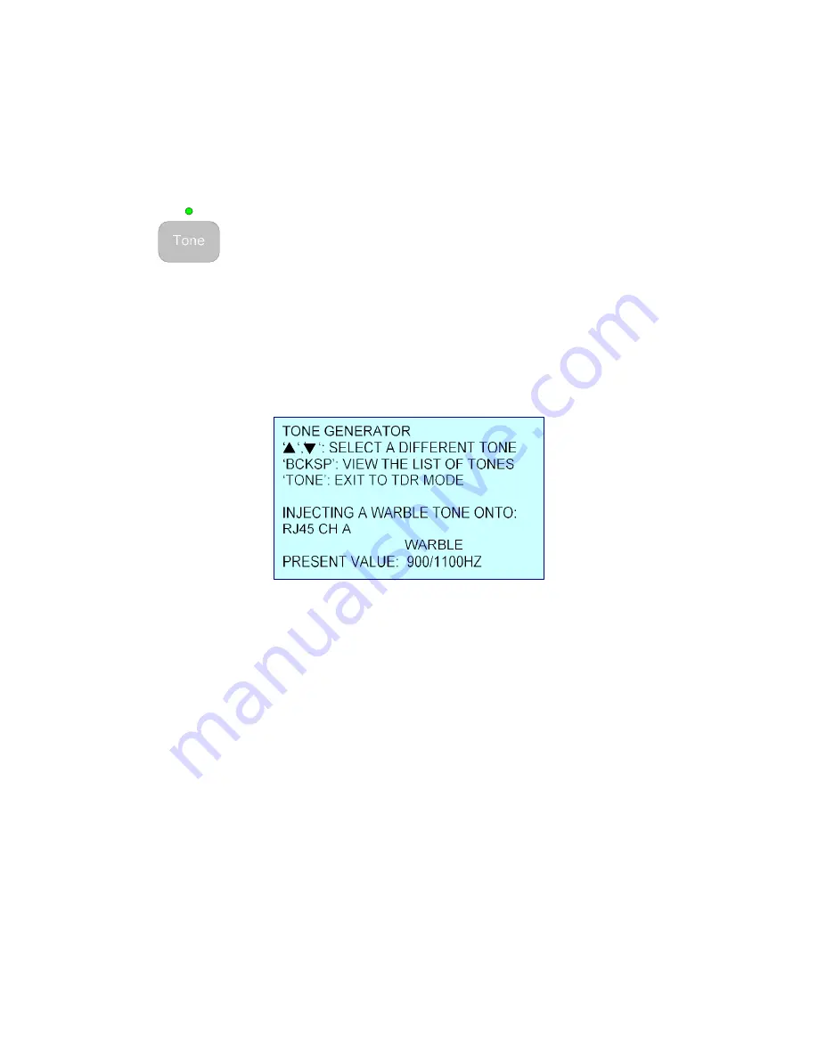
The
key is activated when pressed and the green LED is lit. A Tone
menu will be presented in the LCD as shown in Figure 2-10. Use the
▲▼
keys to
select the tone frequency desired and the
◄►
keys to select having the tone
steady or warbled. Items with a frequency shown will cause the TDR to generate
that frequency on the cable. Standard inductive amplifiers (Probes) will pick up
the tone to ID the cable or cable pair. If “Pocket Toners” are selected the TDR
will generate the DC voltage required to turn on their tone attachment at the far
end of the cable.
Figure 2-10
NOTES: 1. Toner should be used on battery power only. Use with the AC
charger connected will cause 50/60Hz interfere with the tone
frequencies.
2. When the Tone feature is active the TDR measurement will not be
active.
3. When the Tone feature is active the Battery Saver time-out will be
suspended to prevent automatic turn-off of the TDR.
The information in Section 2 is for basic operation. Full cable parameters, testing
explanations, test and measurement setups, and example traces are covered in
Section 3.
NOTE: Avionics TDR users should pay particular attention to Section 3
pages 52 – 54 concerning testing Single-Wires in a harness. Their testing
presents some unique cable impedance changes throughout the harness
that requires complete understanding to correctly interpret the Avionics
TDR’s traces.