25
Section 3 – Test and Measurement Setups
Introduction
Sections 1 and 2 in this manual and the TDRs’ Basic Guide describe the TDR,
menus, Function keys, and provide a general background on how the TDR
operates. This section of the manual will expand on that information to provide:
•
Basic test setups and measuring coax, twisted pair, and other cable types
•
Background on cables’ impedance, velocity factor, and loop resistance
•
More complex test setups and measurements
•
Advanced features in the TDR
Coax Test Setups
Coaxial cable, aka coax,
comes in thousands of styles, types, and brands. All
are constructed around a single premise. It uses a center conductor surrounded
by a shield and the two are separated by a dielectric material or air. The shield is
not a passive element, but an interactive conductor along with the center
conductor. Together they can provide a relatively high quality, low loss, signal
path to transport RF signals from a transmitter to an antenna or antenna to a
receiver or between transmitter and receiver equipment i.e. CATV broadband
media. Having a properly grounded shield around the center conductor also
works to counter-act on electro-magnetic interference (EMI), aka “ingress.”
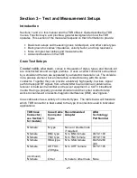
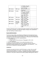
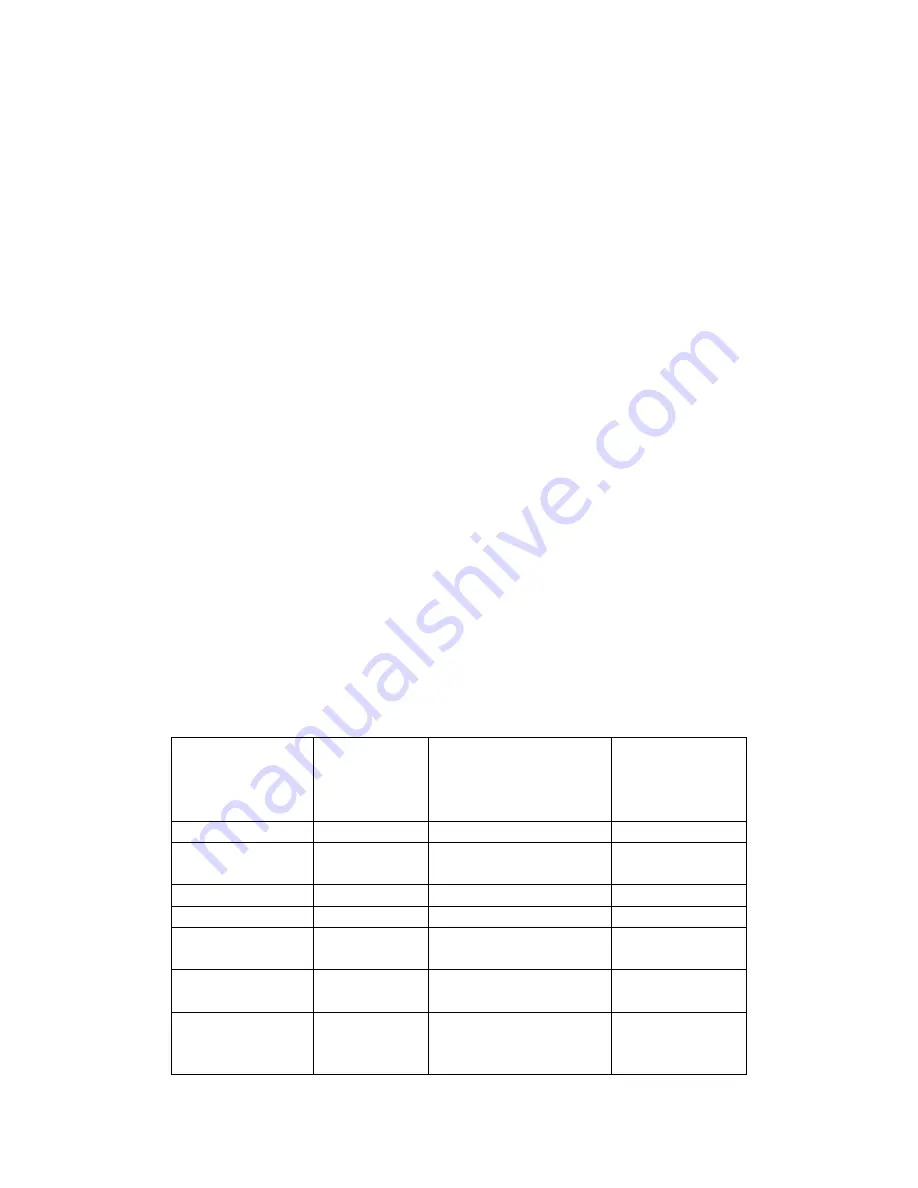
Coax cable also has a variety of connector types. The table below will translate
which TDR connector is best suited to the type of connectors used in individual
applications:
TDR Coax
Connector (
see Section 1
for models)
Coax Cable
Connector
Type
Recommended
Adapter
AEA
Technology
Part Number
N female
N type
None or double male
if required
N female
BNC type
N to BNC female
0070-1190
N female
TNC type
N to TNC female
0070-1134
N female
SMA type
N to SMA female
6025-0260
(kit)
N female
UHF SO-
239 type
N to UHF female
0070-1195
(continued)
N female
Other
N male to other male
None

