27
SWR (Standing Wave Ratio). All systems will have some VSWR, but when
measured, a low ratio is better (1:1.25 in radio systems or less is generally good).
All systems have their designed maximum acceptable VSWR. If a cable’s
impedance is not within its specifications or the cable has deviations due to
damage, poor connections, moisture, etc. this will increase the VSWR. This is
where using a Step TDR to measure the cable’s impedance becomes critical.
Coax cables come in a variety of impedances. Their impedance is designed in
by the manufacturer and in most high quality coax will be very close to the
published specified impedance. Additionally, the specification will have a +/-
value associated with the impedance that should be noted. The following table is
a list of popular impedances and their common applications.
Coax Impedance (Z
0
)
Common Applications
50 and 52 Ohm
Almost all RF communications or radio
applications including broadcast, land
and marine mobile, cellular, amateur
radio (HAM), etc.
62.5 Ohm
Specialized broadband applications.
Example is the old Ethernet thinnet and
thicknet applications now considered
obsolete
75 Ohm
Video mainly CATV and CCTV
systems
93 -125 Ohm
Special applications not commonly
used
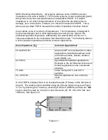
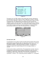
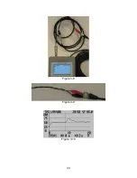
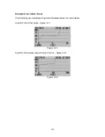
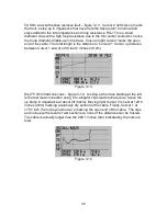
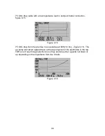
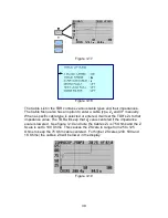
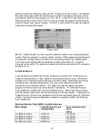
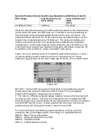
On the TDR’S’s display there is an impedance scale (Z Scale) on the left side of
the plot. The scale can be controlled using the Z Scale function key (see Figure
3-1) or by pressing the Trace key, selecting Z SCALE (OHMS), and use the
◄►
keys to step the scale up or down in set increments (20, 50, 100, 200, 500, and
1KOhms). See figure 3-2.
Figure 3-1

