28
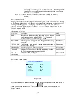
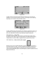
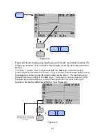
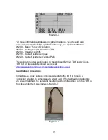
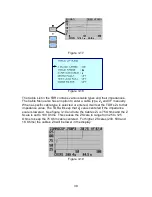
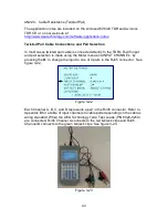
Figure 3-2
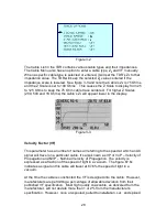
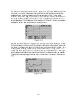
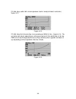
The Cable List in the TDR contains various cable types and their impedances.
The Cable Menu also has an option to enter a cable type, Z
0
and VF manually.
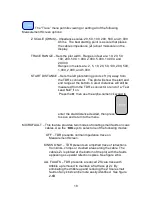
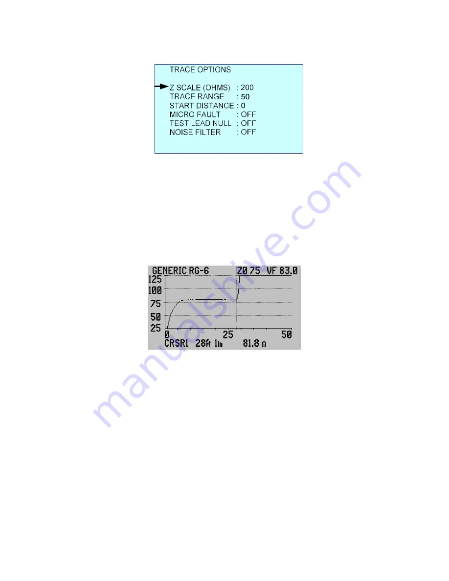
When a specific cable type is selected or entered, it will set the TDR’s Z
0
to that
impedance value. The TDR will keep the selected Z
0
value centered if the
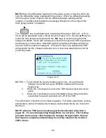
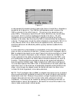
impedance scale is lowered. See figure 3-3 and note the Cable’s Z
0
is 75 Ohms
and the Z Scale is set to 100 Ohms . This causes the Z Scale to display from 25
to 125 Ohms to keep the 75 Ohm cable trace centered. For higher Z Scales
(200, 500 and 1K Ohms) the cable’s Z
0
will appear lower in the display.
Figure 3-3
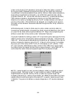
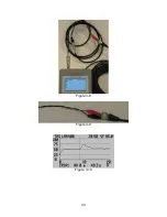
Velocity Factor (VF)
This parameter has a number of names all referring to the speed at which an AC
signal will travel on a particular cable. It’s also known as VP or VoP – Velocity of
Propagation and NVP – Nominal Velocity of Propagation. The velocity is
expressed as a fraction of the speed of light in a vacuum. The figure 67.6c
indicates a signal on this cable will travel at 67.6% the speed of light in a
vacuum.
At the time the cable is constructed the VF is designed into the cable. However,
manufacturers are permitting a percentage of allowable deviation from their
published VF specification. Most high quality coax cable, as delivered from the
manufacturer, will not deviate more than 1 or 2% from the manufacturer’s
specification. However, once un-spooled, pulled to installation, cut, and spliced