
30
Loop Resistance
Loop resistance is defined as the DC resistance of the two conductors in a cable
as measured by an Ohm meter at one end and having a zero Ohm short
between the conductors at the opposite end of the cable. In the case of a coax
cable, that would be a short between the center conductor and shield.
Resistance specifications are normally published separtely for the center
conductor and shield as the DC resistance in one direction over 1000 feet
(300m). The center conductor will have the higher resistance and the shield a
lower resistance due the nature of their construction. To calculate the total loop
resistance, add the two resistances, center conductor and shield. Since this
value is linear over the length of the cable it will divide evenly for shorter lengths.
100ft (30m) of cable will have 10% the loop resistance as the total calculated
value for 1000 feet (300m) of the same cable.
While the Ohm meter requires a zero Ohm short be placed on the conductors at
the far end of the cable to read the loop resistance, the TDR does not. It will add
in the loop resistance for the conductors being measured whether the far end is
open or shorted. This added resistance will cause the TDR’s trace to have an
upward slope over the length of the conductors known as “Dribble-up.” The
amount of dribble-up is relative to the amount of DC loop resistance that is added
to the impedance measurement. Cables with relatively small center conductors
will have higher loop resistances than cables with larger center conductors. As
an example: 75 Ohm hard-line cables which have diameters ranging from about
.400 to 1.125 inches (10mm to 32mm) will have nominal loop resistances of 10 to
2 Ohms/1kft (300 meters) respectively. However, 75 Ohm drop cable
(significantly smaller and more flexible) will have a nominal loop resistance of 25-
40 Ohms/1kft (300 meters) depending on type and brand.
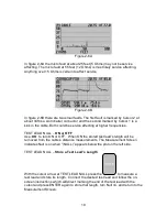
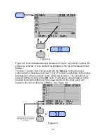
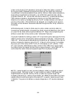
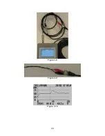
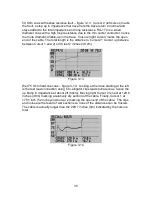
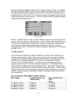
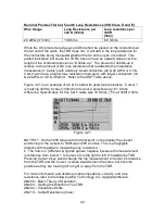
Figure 3-5 is an example of how adding the resistance to the impedance
measurement can be valuable in finding poorly performing cables. Cursor 2 is
positioned on the end of 50 Ohm test lead at 6ft 3inches (1.9m) and reads
relatively close (-1.2 Ohms) from specification. Cursor 1 (data not shown) is
positioned at the end of the 50 foot (15.2m) cable. The CRSR
∆
(difference)
reading between the cursors shows an 11.3 Ohm gain over 50 feet. The cause
is a combination of slightly high impedance at the cable’s start and loop
resistance shown by the dribble-up in the trace. While the dribble-up may be
within specification, added to the higher than specified impedance this cable is
less than optimum for use in a 50 Ohm system.