38
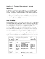
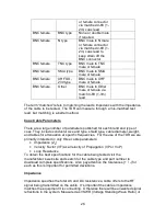
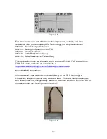
E20/20 TDRs with only an N or BNC connector can be connected to twisted pair
wire and tested as well as using the RJ-45 connector found on Network models.
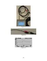
Both the N and BNC models are provided with BNC-to-alligator clips test leads.
Additionally, the N model includes an N-to-BNC adapter. These can be used to
test twisted pair cables one pair at a time. If the Cable List does not include the
type of twisted pair cable desired, one or more cables can be copied from other
cable lists included with ETDR PC Vision software or a cable can be manually
entered or edited into the TDR’s Cable List. Refer to Section 5 for using ETDR
PC Vision for uploading, downloading, and editing cable lists in the software.
Twisted Pair Cable Parameters
There are a large number of parameters published for each brand and type of
twisted pair. They include conductor size and type, shield type (if shielded), cable
diameter, weight, and tables for attenuation at specific frequencies. For the use
of the TDR we are primarily interested in only three cable parameters:
•
Impedance (Z
0
)
•
Velocity Factor (VF) aka Velocity of Propagation (VP or VoP)
•
Loop Resistance
To obtain the best specifications for the cable being tested visit the
manufacturer’s web site and search for the cable type and part number to
download complete specifications. Also pay attention the tolerances (+ / -) for
each as this is important for permitted deviations.
Impedance
Impedance specifies the resistance a cable offers to the AC signal being
transmitted on the cable. It’s important the cable’s impedance matches the
equipment it is connecting with, otherwise there will be unwanted signal
reflections in the system. This is referred to as VSWR (Voltage Standing Wave
Ratio) or SWR (Standing Wave Ratio). All systems will have some VSWR, but
when measured, a low ratio is better (1:1.25 in systems or less is generally
good). All systems have their designed maximum acceptable VSWR. If a
cable’s impedance is not within its specifications or the cable has deviations due
to damage, poor connections, moisture, etc. this will increase the VSWR. This is
where using a Step TDR to measure the cable’s impedance becomes critical.
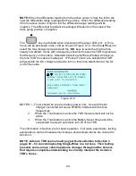
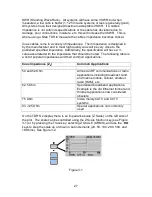
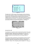
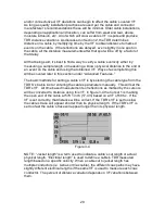
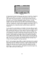
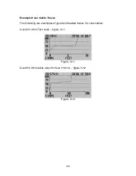
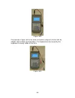
On the TDR’S’s display there is an impedance scale (Z Scale) on the left side of
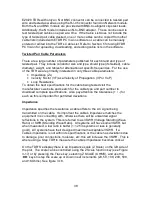
the plot. The scale can be controlled using the Z Scale function key (see Figure
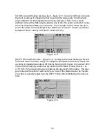
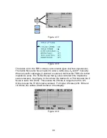
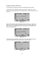
3-17) or by pressing the Trace key, selecting Z SCALE (OHMS), and use the
◄►
keys to step the scale up or down in set increments (20, 50, 100, 200, 500,
and 1KOhms). See figure 3-18.

