

40
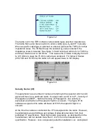
Velocity Factor (VF)
This parameter has a numbers of names all referring to the speed at which an
AC signal will travel on a particular cable. It’s also known as VP or VoP – Velocity
of Propagation and NVP – Nominal Velocity of Propagation. The velocity is
expressed as a fraction of the speed of light in a vacuum. The velocity of 67.6c
indicates a signal on this cable will travel at 67.6% the speed of light in a
vacuum.
At the time the cable is constructed the VF is designed into the cable. However,
manufacturers are permitted a percentage of allowable deviation from their
published specification VF specification. Most high quality twisted pair cable, as
delivered from the manufacturer, will not deviate more than 2-3% from the
manufacturer’s specification. TIA standards for Cat 3 – Cat 6A permit as much
as + 6% However, once un-spooled, pulled to installation, cut, and spliced and/or
connectorized, VF deviations can begin to affect the cable’s overall VF. As long
as quality installation practices are used per the cable and connector
manufacturer’s recommendations these will be minimal. Older cable installation,
depending on application and location, can suffer from wear and tear, abuse,
moisture intrusion, etc. All of which will slow a cable’s VF in spots and produce
TDR distance variations. As discussed in Section 2, the TDR determines
distance on a cable by multiplying time by VF to obtain distance to marked
events on the cable. If the reflections are delayed, even slightly in one spot on
the cable, all the distance measurements after that spot will be off by a factor of
that delay.
Out Side Plant (OSP) telecommunications cables are built to standards that
tightly wrap the pairs inside a shield. This makes the VF factor for those pairs
remain relatively the same from pair to pair. Premise multi-pair cables such as
TIA Cat 2 – Cat 6A (ISO Class A to F) however, tend to have different VF
between different pairs in the same jacket. This is mainly due to two factors: 1.
When compared against jacket length the different twist ratios of the pairs make
them physically longer or shorert than the other pairs in the jacket. Hence, when
a single VF is used to measure each of the 4 pairs they will display different
lengths. 2. Each pair was produced on a different machine or different part of the
machine to achieve the different twist ratios. This induces another opportunity for
the VF to be slightly different between pairs in the same jacket.
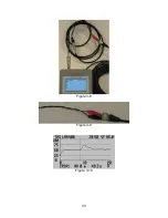
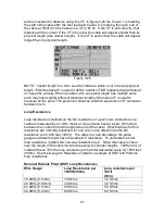
All that being said, it’s best to find a way to verify a cable’s velocity either by
measuring a sample length or measuring a known physical distance to the end or
an event on the cable and using that obtained VF. Ways of accomplishing this
will be covered later in this section under “Advanced Features.”
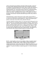
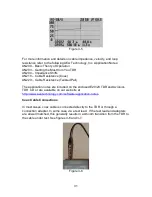
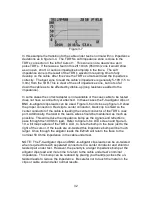
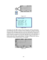
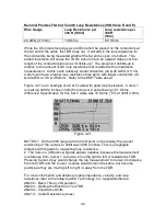
The basic methods for setting a cable’s VF is by selecting the cable type from the
TDR’S’s Cable List or entering the cable’s parameters manually. This will set the
TDR’s VF. All time based measurements of reflections as marked by the cursors