
41
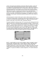
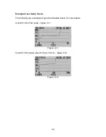
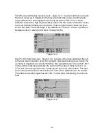
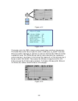
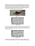
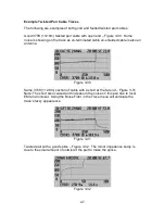
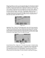
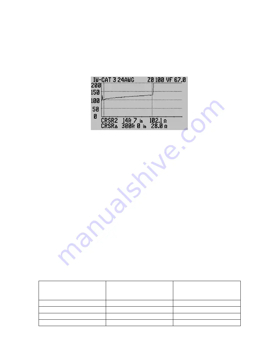
will be converted to distance using this VF. In figure 3-20 the Cursor 1 is marking
the start of the cable after the test lead and Cursor 2 is marking the open end of
the cable at 300ft (91.4m) based on a VF of 67.0c. If the VF is set correctly, that
distance will be correct. If the VF is too slow the cable will appear shorter than its
physical length (aka Jacket Length). If the VF is set too fast the cable will appear
longer than its physical length.
Figure 3-20
NOTE: “Jacket length” is a term used to indicate a cable’s cut or actual physical
length. “Electrical length” is used to define a cable’s TDR measured length based
on a specific velocity. When a cable cut to one jacket length has multiple pairs,
each may have slightly different electrical lengths if the same VF is used to
measure all the pairs. The percent of distance variation depends on VF variations
between them.
Loop Resistance
Loop resistance is defined as the DC resistance of a pair’s two conductors in a
cable as measured by an Ohm meter at one end and having a zero Ohm short
between the conductors at the opposite end of the cable. Specifications for this
resistance are normally published for one wire in one direction as the DC
resistance over 1000 feet (300m). The wires in a pair are always the same
gauge and therefore will have the same DC resistance. To calculate the total
loop resistance, multiply the one-way resistance by 2. Since this value is linear
over the length of the cable it will divide evenly for shorter lengths. 100ft (30m) of
cable will have 10% the loop resistance as the total calculated value for 1000 feet
(300m). See the Gauge to Resistance Table for a sample of OSP and Premise
loop resistances:
Nominal Outside Plant (OSP) Loop Resistances
Wire Gauge
Loop Resistance per
1000ft (300m)
Loop resistance per
100 ft
(30m)
19 AWG (0.9mm)
16 Ohms
1.6 Ohms
22 AWG (0.64mm)
32 Ohms
3.2 Ohms
24 AWG (0.5mm)
50 Ohms
5.0 Ohms
26 AWG (0.4mm)
80 Ohms
8.0 Ohms


