42
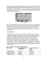
Nominal Premise TIA Cat 5 and 6 Loop Resistances (ISO Class D and E)
Wire Gauge
Loop Resistance per
328 ft (100m)
Loop resistance per
100ft
(30m)
24 AWG (0.5mm)
19 Ohms
6.0 Ohms
While the Ohm meter requires a zero Ohm short be placed on the conductors at
the far end of the cable, the TDR does not. It will add in the loop resistance for
the conductors being measured whether the far end is open or shorted. This
added resistance will cause the TDR’s trace to have an upward slope over the
length of the conductors known as “Dribble-up.” The amount of dribble-up is
relative to the amount of DC loop resistance that is added to the impedance
measurement. Cable’s with relatively small conductors (24 & 26 AWG or 0.5 &
0.4mm) will have a higher loop resistance than pair’s with larger conductors (19
& 22 AWG or 0.9 & 0.64mm). Refer to the OSP Table above.
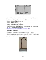
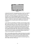
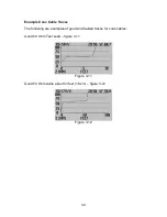
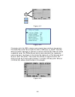
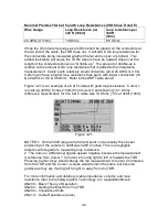
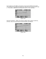
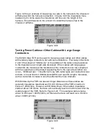
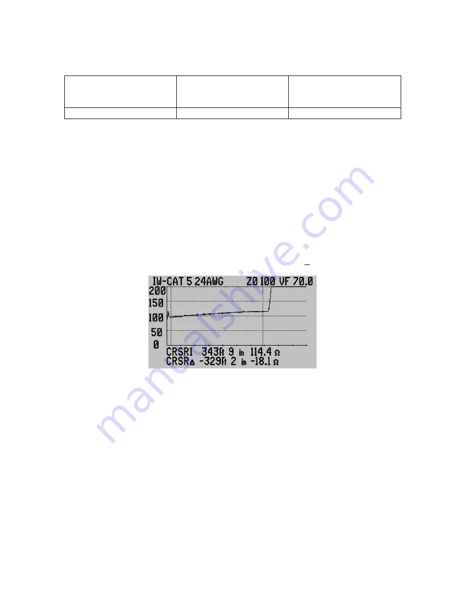
Figure 3-21 is an example of a Cat 5 cable with good loop resistance. Cursor 1
is marking 329ft 2 inches (100m) from Cursor 2 and showing 18.1 Ohms
difference. Specification for this Cat 5 cable was 19 Ohms + 5% at 328ft (100m)
Figure 3-21
NOTES: 1. On the 500ft range with 240 plot point on the display the closest
positioning of the cursors to 328ft was 329ft 2 inches. This is a negligible
distance with regards to measuring loop resistance.
2. The Cursor
∆
(difference) figures appear negative because the measurement
is reference from Cursor 1 to Cursor 2 moving right to left or towards the TDR.
Pressing Cursor 2 key would change the top measurement to Cursor 2’s distance
from the TDR and the Cursor
∆
values would remain the same, but become
positive as they are moving left to right or away from the TDR.
For more information and details on cable impedance, velocity, and loop
resistance refer to the following AEA Technology, Inc. Application Notes:
AN200 – Basic Theory of Operation
AN203 – Getting the Most from You TDR
AN204 – Impedance Shifts
AN210 – Cable Resistance (Coax)

