
43
AN220 – Cable Resistance (Twisted Pair)
The application notes are included on the enclosed E20/20 TDR and Avionics
TDR CD or on our web site at
http://www.aeatechnology.com/software/application-notes
.
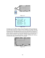
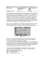
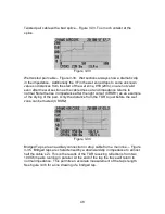
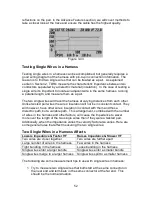
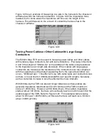
Twisted Pair Cable Connections and Pair Selection
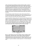
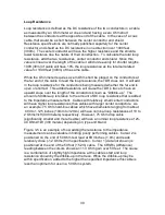
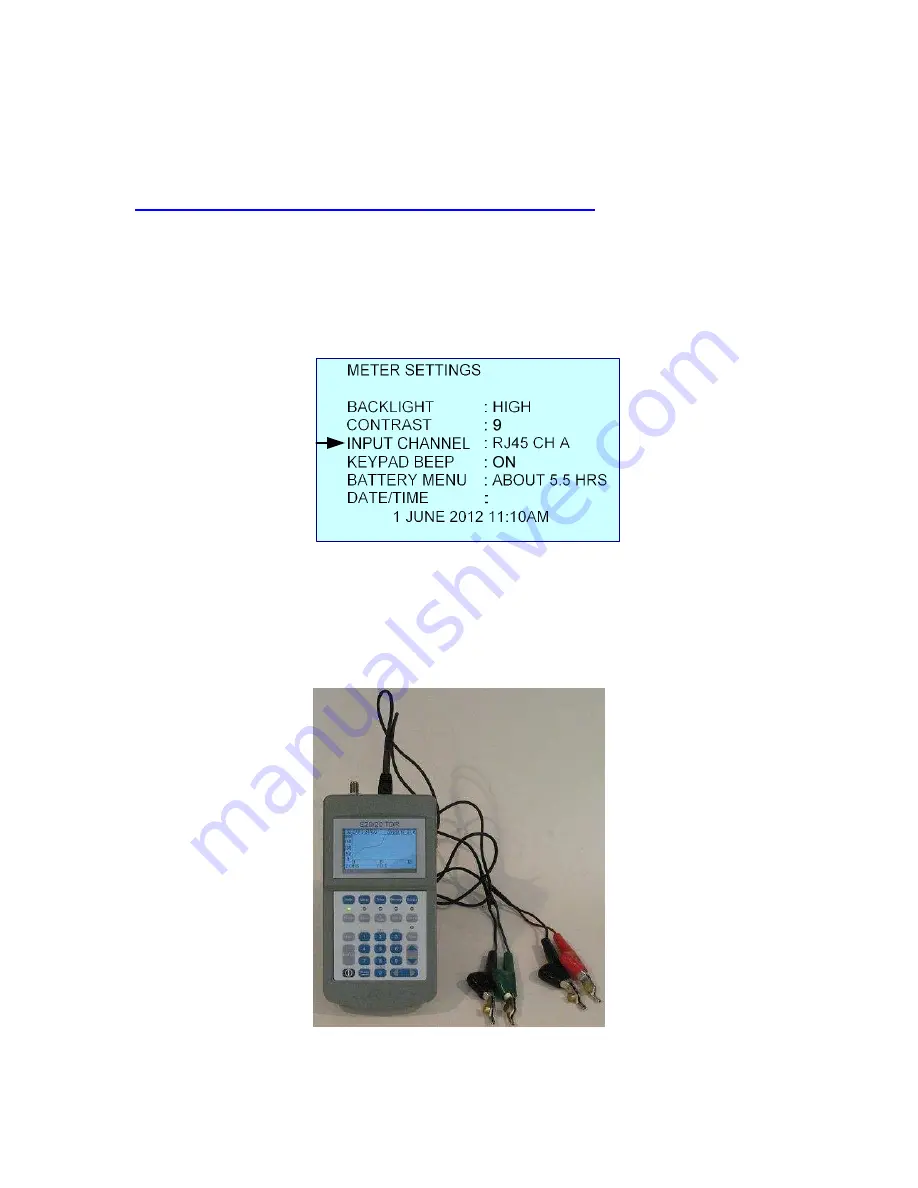
In most cases twisted pair cable is connected directly to the TDR’s RJ-45 input
and pair selection is made using the Meter menu and INPUT CHANNEL: by
pressing the
►
to change the input to one of 4 pairs in the RJ45 connector. See
figure 3-22.
Figure 3-22
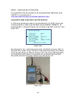
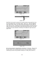
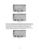
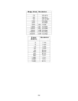
Each Channel A, B, C, and D represents a pair in the RJ45 connector. Refer to
Appendix B for a table of input channels to cable pairs depending on the cable’s
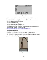
wiring standard. When the AEA Technology Telco Test Leads (P/N 6020-0250)
are connected, RJ45 Channel A connects to the red & black clips and RJ45
Channel B connects to the green & black clips. See figure 3-23.
Figure 3-23