
45
on the enclosed E20/20 TDR and Avionics CD or from our web site at
www.aeatechnology.com
.
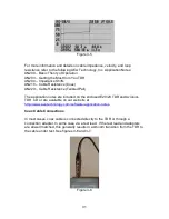
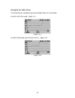
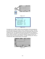
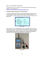
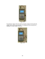
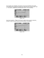
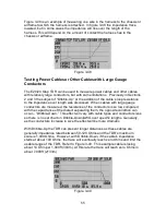
The other way to connect a cable to the RJ-45 port is directly using either an
RJ-45 (4 pair), RJ-12, (3 pair), or RJ-11 (2 pair) connectors. This type of
connection negates having any impedance bump at the start of a trace. See
figure 3-27. RJ-45 Channel to test pair selection is per the table in Appendix B.
Figure 3-27
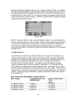
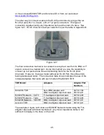
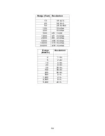
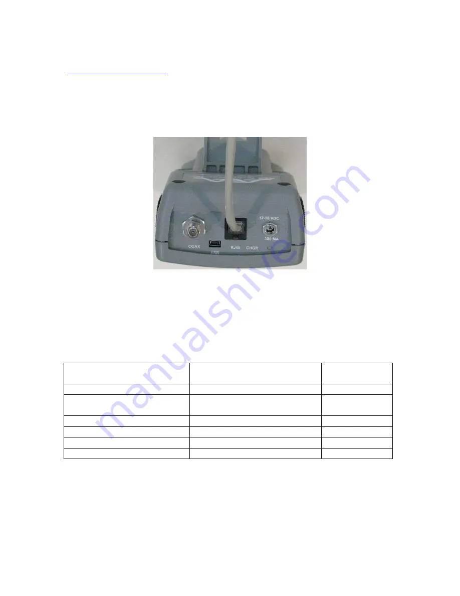
The final connection method to be covered is using the Coax Port; N, BNC or F
style to connect to a twisted pair. Using this method you lose the capability to
connect up to 4 pairs at one time and selecting them via the RJ-45 port’s
Channels. However, if using a model without an RJ-45 Port, this still permits
testing twisted pair cable. The connection table shown indicates the use of the
included adapters that came with each model of the E20/20 TDR.
TDR Model
Adapters
Adapter Part
Numbers
E20/20N TDR
N-to-BNC adapter and
BNC to alligator clips test lead
0070-1190
0070-1221
E20/20F Network – CATV
F-to-alligator clips test lead
0070-1220
E20/20F Network – Telco
F-to-alligator clips test lead
0070-1220
E20/20B Network – VDV/RF
BNC to alligator clips test lead
0070-1221
Avionics TDR
BNC to alligator clips test lead
0070-1221
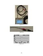
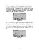
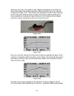
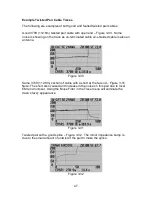
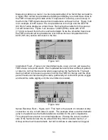
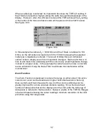
The example in figure 3-28 shows an E20/20F Network model using the F-to-
alligator clips lead with twist maintained. Any minor impedance bump is not
sufficient to display in the trace on the LCD.