

55
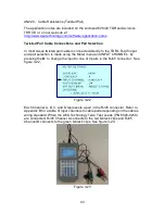
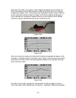
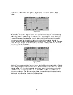
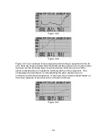
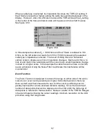
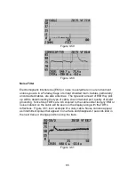
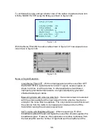
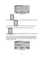
Figure 3-48 is an example of measuring one wire in the harness to the chassis or
airframe to which the harness is attached. In figure 3-48 the impedance trace
lowered, but in some cases the impedance will rise over the length of the
harness. This will depend on the amount of contact the harness has to the
chassis or airframe.
Figure 3-48
Testing Power Cables or Other Cables with Large Gauge
Conductors
The E20/20 Step TDR can be used to measure power cables and other cables
with relatively large conductors, but with some limitations. Previously in Sections
2 and 3 the subject of “Dribble-Up” or the addition of the cable’s loop resistance
to the impedance over length was discussed. When cables with large gauge
conductors are measured, the resistance of the conductors is so low compared
with the capacitance of the dialect separating them, the opposite condition can
occur – “Dribble-Down.” This affect will vary with cable types and conductor sizes
so there is no set chart on Dribble-Down/AWG over specific lengths. Generally,
as the conductors increase in size the effect will be more dramatic.
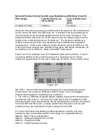
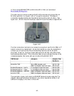
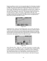
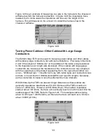
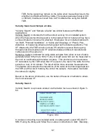
With Dribble-Up the TDR can present longer distances as these cables are
generally impedance rated between 50-120 Ohms and the TDR’s maximum
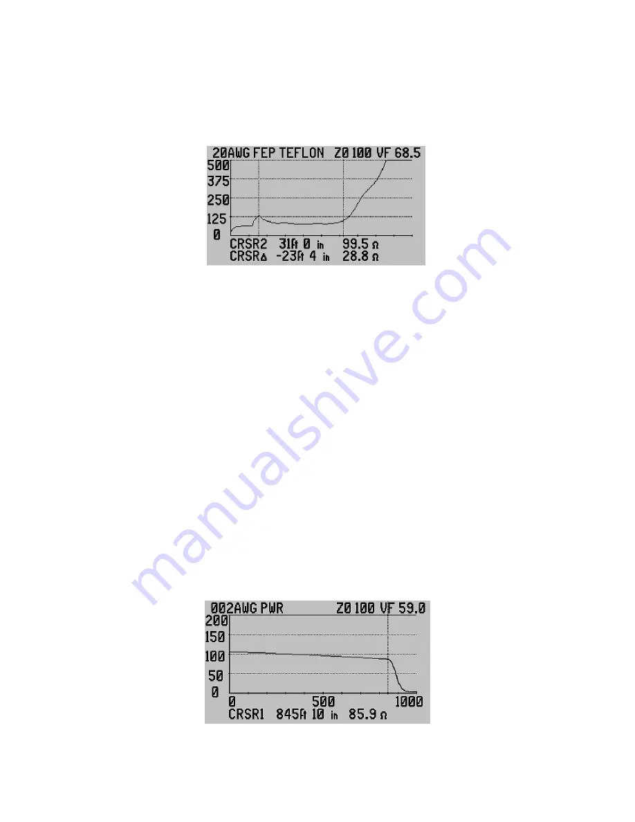
scale is 1,000 Ohms. However, with Dribble-Down, if the cable’s impedance
starts at about 100 Ohms, the trace will eventually reach zero Ohms and limit the
usable range of the TDR. Refer to Figure 3-49. This example cable is losing
about 14 Ohm per 1,000ft (304m). At this rate the trace will reach zero Ohms in
about 7,000ft (2133m).
Figure 3-49