8
Should the microphone source impedance be the same as its load
impedance?
This is a telephone technique from before tubes were invented.
Matching the impedance of a telephone’s microphone with the
load maximized the listener’s volume at the other end of the line.
But now it just increases distortion, decreases headroom, and
degrades transient and frequency response. When a mic’s output
impedance matches the preamp’s input impedance, 6 dB of level
is lost. The noise floor goes up 6 dB and the preamp will need 6 dB
more gain.
The high-impedance design of the TRP500 results in no loss of level
or signal quality due to impedance mismatching.
SETTING THE GAIN
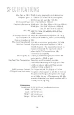
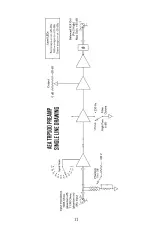
The TRP500’s minimalist JFET circuit design delivers up to 85 dB of
clean, quiet gain. With extended bandwidth from below 10 Hz to
beyond 200 kHz, it delivers effortless dynamic range and transient
response that complements all microphones. Its DC-coupled circuit
extends the low frequency response and speeds recovery to linear
operation after overloads.
As with any piece of audio equipment, setting and maintaining
proper signal levels is critical to obtaining optimum performance. If
the level is set too low, noise performance is sacrificed; if the level
is too high, there’s a risk of overload distortion.
Setting the AEA TRP500 gain begins by setting the first stage GAIN
and second stage OUTPUT knobs fully counterclockwise. The first
stage GAIN control has 12 precision steps from +7 dB to +65 dB.
The second stage OUTPUT potentiometer knob when all the way
down (counterclockwise) adds no gain, and all the way up adds +20
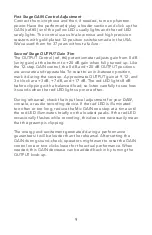
dB. The three LEDs: green, yellow and red (ref.#1) snap on at -20, 0,
and +20 dBu to indicate signal activity.


