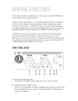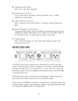
3 - Polarity Invert switch
OUT is normal; IN is inverted.
4 - Output Level control
This continuously variable control provides up to +19dB
additional output gain.
5 - Low-Cut Filter In switch
OUT is bypass; IN inserts 100 Hz, 12 dB per octave high pass
filter.
6 - Audio Signal Level indicators
The green LED snaps on at -20 dBu to indicate the presence of
signal; the yellow LED snaps on at 0 dBu; the red LED snaps on
at +24 dBu to warn of approaching signal overload.
7 - Power switch
OUT is off; IN powers on unit. Green LED above switch will
indicate if unit is on.
CONNECTIONS GUIDE
The TRP2’s rear panel supplies one Neutrik 3-pin XLR input per
channel. Microphone input connections are made via female XLR
connectors with Pin-2 + or high, Pin-3 – or low, and Pin-1 ground.
Mic Input mode can be activated with the Mic/Line switch (ref. #8)
in the OUT position.
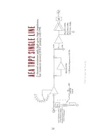
The XLR Input routes through the preamp gain stage, high-pass
filter EQ, and Output Level control to the XLR output.
The output of the TRP2 emulates a transformer-coupled output and
can be used as either a balanced or unbalanced signal (depending
on how your cable/system is configured).
6


