background image

SETTING THE GAIN

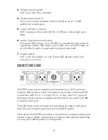
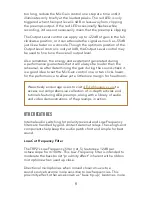
When balanced, the maximum output level is +28 dBu; when 

unbalanced, the maximum level is +22 dBu. (These are as measured 

into a 600 Ohm load; the recommended load is > 10K Ohms; 0 dBu 

= 0.7746 V rms.)

When unbalancing the XLR Output, pin-3 must be tied to ground at 

the receiving end (i.e. the input of the following device). Do not tie 

pin-3 to ground directly at the output of the TRP2.

To prevent damaging the equipment in your system, it is a good 

idea to test your microphone cables regularly to determine whether 

they have any open, shorted, reversed, or intermittent connections.

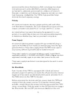
Despite the small half-rack footprint, the TRP2 packs several key 

features that are critical for professional recording. Designed 

by Fred Forssell to handle extreme dynamics, the TRP2 recovers 

instantaneously from unexpected “solid red” overloads. The gain 

structure of the 2-channel (dual mono) preamp consists of an input 

gain control and an output level control.

The TRP2’s JFET circuit design generates up to 85dB of clean 

and quiet gain, with extended bandwidth from below 1 Hz to 

beyond 200 kHz, for dynamic range and transient response that 

complements all microphones. 

As with any piece of audio equipment, setting and maintaining 

proper signal levels are critical to obtaining optimum performance: 

if the level is too low, you sacrifice noise performance; if too 

high, you risk overload distortion. The AEA TRP2 provides an easy 

method for setting and monitoring the system gain.

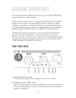
The Mic Gain control (ref. #1) provides from about +7dB to +63dB 

of gain for the preamp input stage. The Output Level control (ref. 

#11) adds a22dB of output gain for a total of +85dB of 

gain. 

Start with the Output Level control (ref. #4) pointing at the 0dB 

indicator and the Mic Gain control fully counterclockwise. Then, 

with the microphone in position increase the Mic Gain control until 

you are happy with the input level in your DAW, console, or tape 

machine. On the TRP2, if the red LED is illuminated too often or 

7

Summary of Contents for TRP2

Page 1: ...OWNER S MANUAL THE ORIGINAL 2 CHANNEL RIBBON PREAMP AEA TRP2 ...

Page 2: ...hance the sound of your ribbons with the right preamp The TRP2 is the perfect companion for any and all ribbons condensers and moving coil microphones whenever a true and pristine signal path is desired Your TRP2 is 100 handcrafted in Pasadena CA AEA is a family owned company with a small crew of skilled technicians most of them being musicians themselves Proudly independent we still manufacture a...

Page 3: ...CONTENTS WELCOME INTRODUCTION WARRANTY SUPPORT GENERALGUIDELINES FRONTPANELGUIDE CONNECTIONSGUIDE SETTINGTHEGAIN OTHERFEATURES SPECIFICATIONS 2 4 4 4 5 5 6 7 8 11 3 ...

Page 4: ...e TRP2 s exceptionally high input impedance of 63 000 Ohms means it will not load down a mic and change its sound The JFET discrete front end provides all the dynamics subwoofer bass and fast transients that your microphones can deliver WARRANTY SUPPORT Your TRP2 comes with a one year limited warranty on parts and labor shipping not included Registering your preamp with AEA will extend the warrant...

Page 5: ...reamp away from these sources in addition to hot surfaces 2 Before turning on the power all connections to the preamp should be made and the gain controls set at their minimum settings Be sure to examine your signal chain before powering up the preamp to ensure sudden loud noises are not emitted which could damage your system or hearing 1 Input Gain rotary switch 12 position Grayhill switch rangin...

Page 6: ...er switch OUT is off IN powers on unit Green LED above switch will indicate if unit is on CONNECTIONS GUIDE The TRP2 s rear panel supplies one Neutrik 3 pin XLR input per channel Microphone input connections are made via female XLR connectors with Pin 2 or high Pin 3 or low and Pin 1 ground Mic Input mode can be activated with the Mic Line switch ref 8 in the OUT position The XLR Input routes thro...

Page 7: ...sists of an input gain control and an output level control The TRP2 s JFET circuit design generates up to 85dB of clean and quiet gain with extended bandwidth from below 1 Hz to beyond 200 kHz for dynamic range and transient response that complements all microphones As with any piece of audio equipment setting and maintaining proper signal levels are critical to obtaining optimum performance if th...

Page 8: ...nd check it is a good idea to set the Mic Gain control one or two clicks lower for the performance to allow yet a little more margin for headroom OTHER FEATURES Internal audio switching for polarity reversal and Low Frequency filters are handled by gold contact Aeromat relays These high end components help keep the audio patch short and simple for best sound Low Cut Frequency Filter The TRP2 s Low...

Page 9: ... with the TRP2 so hum fields can be kept away from the high gain electronics The power supply allows the TRP2 to be used in any country without any modifications made to the unit The power supply is a universal switching supply it provided 3 regulated outputs 18 5VDC and 52VDC these voltages are then regulated internally again to provide clean power for the unit The power supply transformer is not...

Page 10: ...10 TRP2 Single Line Drawing ...

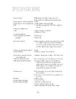
Page 11: ... source 3dB 1Hz and 100 kHz 0 02 at 1 kHz 63K Ohms 10K Ohms Twelve position switch provides from 7dB to 63dB of gain for the preamplifier circuit as measured between the input and the before the output line driver 25dB 12dB per octave from 100 Hz 28 dBu balanced 0 dBu 0 7746 V rms Pin 1 is ground pin 2 is high pin 3 is low The green LED snaps on at 20 dBu to indicate the presence of signal the yel...

Page 12: ...AEARIBBONMICS COM RIBBONMICS INFO RIBBONMICS COM 800 798 9127 ...

Reviews: