126
126
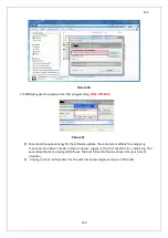
Picture .11
14)
C2000 prog software indicates that the programming is successful, click OK.
15)
After the installation is completed, turn UPS’s input breaker (CB1) off position and see UPS
de-energised. Turn SW2 notch 1 off again.
16)
Turn UPS’s input breaker (CB1)on again and see the main board is energised again. Check
that the correct version is to set in the control panel. This shows that the programming is
successfully done.
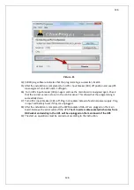
17)
Turn UPS’s input breaker (CB1) off .Plug in J2 sockets instead of external power supply. Plug
in input and battery fuses if they are unplugged.
18)
After the installation is completed, the PWM sockets of J36-J37 are plugged on the main
board. Remove the serial cable off the UPS.
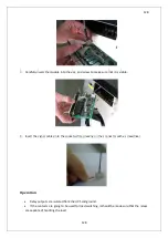
The J1 inverter cable socket which comes from
DB9 socket and existing in the UPS will be unplugged on the main board of the UPS
19)
The start up operations must be carried out according to the instruction.
Summary of Contents for IST5 Series
Page 2: ...2 2 SERVICE MANUAL 10 15 20 30 40 60 80 100 120 160 200 300 KVA...
Page 6: ...9 9 2 PRODUCT DESCRIPTION 2 1 General View 10 15 20 30 40KVA...
Page 7: ...10 10 60 80KVA...
Page 8: ...11 11 100 120 160 200 300 KVA...
Page 13: ...16 16 2 5 Side Interior View 10 15 20 30 40KVA...
Page 16: ...19 19 2 7 Electrical Connections...
Page 35: ...38 38...
Page 36: ...39 39...
Page 51: ...54 54 30 40KVA 60 80 100 120 160 200 300 KVA...
Page 54: ...57 57...
Page 71: ...74 74 1 Turn CB2 ON 10 15 20KVA 30 40KVA...
Page 72: ...75 75 60 80 100 120KVA 2 Stop the UPS using the user front panel Main menu Control Stop...
Page 73: ...76 76 3 Turn CB1 CB3 and CB4 OFF 10 15 20KVA 30 40KVA...
Page 100: ...103 103 Signal Flow Diagram zole trafo means isolated transformer...
Page 102: ...105 105 20 30KVA IGBT Driver 40KVA IGBT Driver...


