21
21
2.8.1 Static Transfer Switch
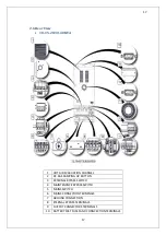
Some blocks are named as “static switches” as can be seen above. These blocks consist of inverse
parallel connected thyristors. Controlled by the main board control unit (DSP) these switches
provide feeding of the loads through either mains or inverters. The loads are supplied through
inverter during the normal operating mode. Therefore, Inverter static switches are active if
there are no problems with the system.
System provides the loads to be fed smooth and seamless by mains or inverter. In order to
manage this process at minimum risk, UPS synchronizes the inverter output and static (mains)
bypass as phase and frequency. Therefore, Inverter frequency can be considered same with
mains as long as it is within frequency limit.
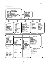
User can switch between mains and inverter by using front panel. When the inverter is ready,
while the loads are fed through the bypass line, in case of either power failure or if mains values
are out of tolerances, the loads automatically will be fed through the inverter.
2.8.2 Battery Temperature Regulation
In the external battery cabinets the battery temperature is measured and detected by
‘’temperature sensor’’. UPS adjusts battery charge parameters according to the detected
temperature.
2.9 UPS’s Operation Modes
IST5 series is on-line double conversion device. Our products operate in the following
modes:
Online Mode
Battery Mode
Bypass Mode
Auto Restart
Maintenance Mode
Summary of Contents for IST5 Series
Page 2: ...2 2 SERVICE MANUAL 10 15 20 30 40 60 80 100 120 160 200 300 KVA...
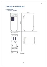
Page 6: ...9 9 2 PRODUCT DESCRIPTION 2 1 General View 10 15 20 30 40KVA...
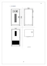
Page 7: ...10 10 60 80KVA...
Page 8: ...11 11 100 120 160 200 300 KVA...
Page 13: ...16 16 2 5 Side Interior View 10 15 20 30 40KVA...
Page 16: ...19 19 2 7 Electrical Connections...
Page 35: ...38 38...
Page 36: ...39 39...
Page 51: ...54 54 30 40KVA 60 80 100 120 160 200 300 KVA...
Page 54: ...57 57...
Page 71: ...74 74 1 Turn CB2 ON 10 15 20KVA 30 40KVA...
Page 72: ...75 75 60 80 100 120KVA 2 Stop the UPS using the user front panel Main menu Control Stop...
Page 73: ...76 76 3 Turn CB1 CB3 and CB4 OFF 10 15 20KVA 30 40KVA...
Page 100: ...103 103 Signal Flow Diagram zole trafo means isolated transformer...
Page 102: ...105 105 20 30KVA IGBT Driver 40KVA IGBT Driver...


