25
25
Deep Discharge Protection
While the system is operating in the battery mode, if battery voltage has dropped below the
discharge level UPS shuts down and stops taking energy from the batteries. This value varies
between 1.6-1.75 V/cell for Lead-Acid batteries, and between 0.9-1.1 V / cell for Ni-Cd batteries.
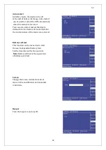
Low Battery Warning
While the system operates on battery (stored) mode, according to actual loads, if the battery
capacity drops below 40% of its value, device will give audible and visible alarms. This value is
adjustable and can be set by user between 20%-70%.
2.10.2 Advanced Functions (Battery test) Auto Battery Test
The auto battery test discharges 10% of the battery energy in a user defined period. Default is 90
days. Test reports the battery condition as good, weak or replace. Results of the latest test can be
seen on the battery screen from the status menu.
WARNING: If the test result is “replace”, then batteries are
completely drained during the test. This may cause the interruption
in the power supply to the critical loads in case of the mains failure.
This test command can be given from front panel monitor, via TELNET interface, via RS232
smart communication or via UPSMAN (SNMP, see the options).
The purpose of the battery test is to check if the batteries can supply the minimum back-up time
needed in case of mains failure. We recommend checking the test results on the regular basis.
Summary of Contents for IST5 Series
Page 2: ...2 2 SERVICE MANUAL 10 15 20 30 40 60 80 100 120 160 200 300 KVA...
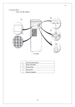
Page 6: ...9 9 2 PRODUCT DESCRIPTION 2 1 General View 10 15 20 30 40KVA...
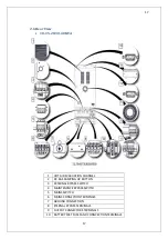
Page 7: ...10 10 60 80KVA...
Page 8: ...11 11 100 120 160 200 300 KVA...
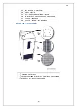
Page 13: ...16 16 2 5 Side Interior View 10 15 20 30 40KVA...
Page 16: ...19 19 2 7 Electrical Connections...
Page 35: ...38 38...
Page 36: ...39 39...
Page 51: ...54 54 30 40KVA 60 80 100 120 160 200 300 KVA...
Page 54: ...57 57...
Page 71: ...74 74 1 Turn CB2 ON 10 15 20KVA 30 40KVA...
Page 72: ...75 75 60 80 100 120KVA 2 Stop the UPS using the user front panel Main menu Control Stop...
Page 73: ...76 76 3 Turn CB1 CB3 and CB4 OFF 10 15 20KVA 30 40KVA...
Page 100: ...103 103 Signal Flow Diagram zole trafo means isolated transformer...
Page 102: ...105 105 20 30KVA IGBT Driver 40KVA IGBT Driver...


