51
51
1.
Remove the battery fuse.
2.
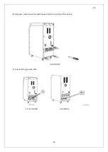
Make sure that the batteries are connected properly in series and parallel.
3.
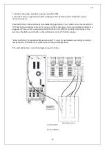
Reach the –BAT labeled cable inside the UPS and connect it to the negative battery terminal.
4.
Reach the +BAT labeled cable inside the UPS and connect it to the positive battery terminal.
5.
Check the polarity of the battery connection once again.
6.
Replace the metal rear cover.
Avoid short circuit in the batteries. Short circuited batteries are hazardous
to human health and environment!
Battery terminal may rise up to 450 Vdc.
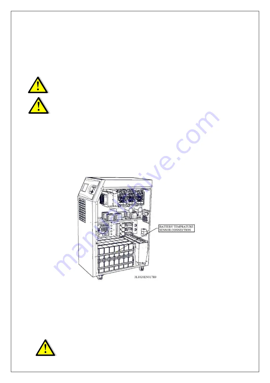
Battery temperature monitoring
Internal battery temperature is monitored by the NTC connected to the J26 socket of the main
board. Refer to the options section for external battery monitoring.
3.1.5.4.2 External Battery Installation Procedure and Connection (30-40-60-80-
120-160-200KVA)
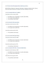
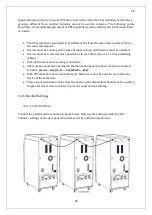
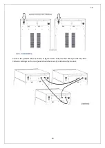
You can find details about how to configure external batteries above under “External Batteries
Configuration” title.
The information about connection of external batteries and UPS is given in this section.
Summary of Contents for IST5 Series
Page 2: ...2 2 SERVICE MANUAL 10 15 20 30 40 60 80 100 120 160 200 300 KVA...
Page 6: ...9 9 2 PRODUCT DESCRIPTION 2 1 General View 10 15 20 30 40KVA...
Page 7: ...10 10 60 80KVA...
Page 8: ...11 11 100 120 160 200 300 KVA...
Page 13: ...16 16 2 5 Side Interior View 10 15 20 30 40KVA...
Page 16: ...19 19 2 7 Electrical Connections...
Page 35: ...38 38...
Page 36: ...39 39...
Page 51: ...54 54 30 40KVA 60 80 100 120 160 200 300 KVA...
Page 54: ...57 57...
Page 71: ...74 74 1 Turn CB2 ON 10 15 20KVA 30 40KVA...
Page 72: ...75 75 60 80 100 120KVA 2 Stop the UPS using the user front panel Main menu Control Stop...
Page 73: ...76 76 3 Turn CB1 CB3 and CB4 OFF 10 15 20KVA 30 40KVA...
Page 100: ...103 103 Signal Flow Diagram zole trafo means isolated transformer...
Page 102: ...105 105 20 30KVA IGBT Driver 40KVA IGBT Driver...


