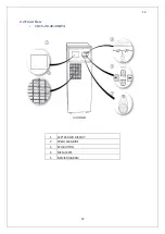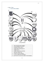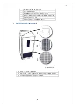
8
8
1.2 Clearance and Access
Clearance
There is no any air inlet or outlet grill on the left or right sides of our 10-20 kVA UPS. All air goes
in to UPS from the front and is evacuated from the rear through fans. There must be spaces at
least 1 meter for UPS's front side and 1,2 meter at the back side. Should not be permanent or
temporary use within the limits specified. Otherwise, the UPS performance will decrease.
Access
Operator reaches UPS via front panel on 10-20 kVA UPS. Therefore, enough area must be left for
operator. Also, UPS can be intervened in the back of it for service and maintenance. Because of
this reason, enough area for personal must be left at the rear side of UPS.
1.3 Storage
UPS should be kept in a room or area where is protected from excessive moisture and heat
before commissioning. UPS and battery cabinets must be kept in the original packaging.
WARNING:
Unused batteries must be charged at regular intervals. This time interval
are determined by the battery supplier. Charging can be performed
periodically by connecting to a proper mains for a while.
1.4 Shipment
Carrying vehicles must have be equipped properly and have features and characteristics
sufficient to carry UPS.
The UPS device shipment must be done on pallets.
The 10-20kVA UPS are delivered on the pallet sized 87x55x140 mm (WxDxH). The height of
device together with pallet is approximately 200mm. The pallet measurements are given below.
Cabinet is equipped with four-wheel. In this way, it can be placed by moving easily. These wheels
are to be used on smooth surfaces only.
The front wheels of UPS must be locked after positioning properly. The rear side wheels are
fixed.
Be more careful of sudden movements, especially when batteries are inside of cabinet.
Move the UPS as rarely as possible
Summary of Contents for IST5 Series
Page 2: ...2 2 SERVICE MANUAL 10 15 20 30 40 60 80 100 120 160 200 300 KVA...
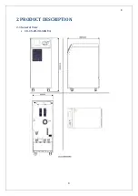
Page 6: ...9 9 2 PRODUCT DESCRIPTION 2 1 General View 10 15 20 30 40KVA...
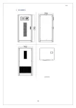
Page 7: ...10 10 60 80KVA...
Page 8: ...11 11 100 120 160 200 300 KVA...
Page 13: ...16 16 2 5 Side Interior View 10 15 20 30 40KVA...
Page 16: ...19 19 2 7 Electrical Connections...
Page 35: ...38 38...
Page 36: ...39 39...
Page 51: ...54 54 30 40KVA 60 80 100 120 160 200 300 KVA...
Page 54: ...57 57...
Page 71: ...74 74 1 Turn CB2 ON 10 15 20KVA 30 40KVA...
Page 72: ...75 75 60 80 100 120KVA 2 Stop the UPS using the user front panel Main menu Control Stop...
Page 73: ...76 76 3 Turn CB1 CB3 and CB4 OFF 10 15 20KVA 30 40KVA...
Page 100: ...103 103 Signal Flow Diagram zole trafo means isolated transformer...
Page 102: ...105 105 20 30KVA IGBT Driver 40KVA IGBT Driver...

