81
81
Testing Board Physically:
Circuit components and PCB should be tested by physically and microscope and IPC-A-610D
CLASS II criteria and assembly directions should be validated.
Bar-coding order should be controlled and validated.
Electrical Tests:
1.
DC 0-900V supply is connected to J3
2.
R60 resistance is connected to DC voltmeter.
3.
In second channel of oscilloscope, negative side of probe is connected to number 3
of Q3 and positive side is connected to number 1 by isolated probe.
4.
In third channel of oscilloscope with isolated probe, negative side of probe is
connected to number 3 of Q1; positive side is connected to number 1. Volt/Div=10V
Offset=-20 are all set. Trigger is set to channel 2 and the slope step should be
pos/time.
5.
Number 1 of J4 socket is applied to zero; number 2 is applied to 15VDC.
6.
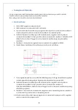
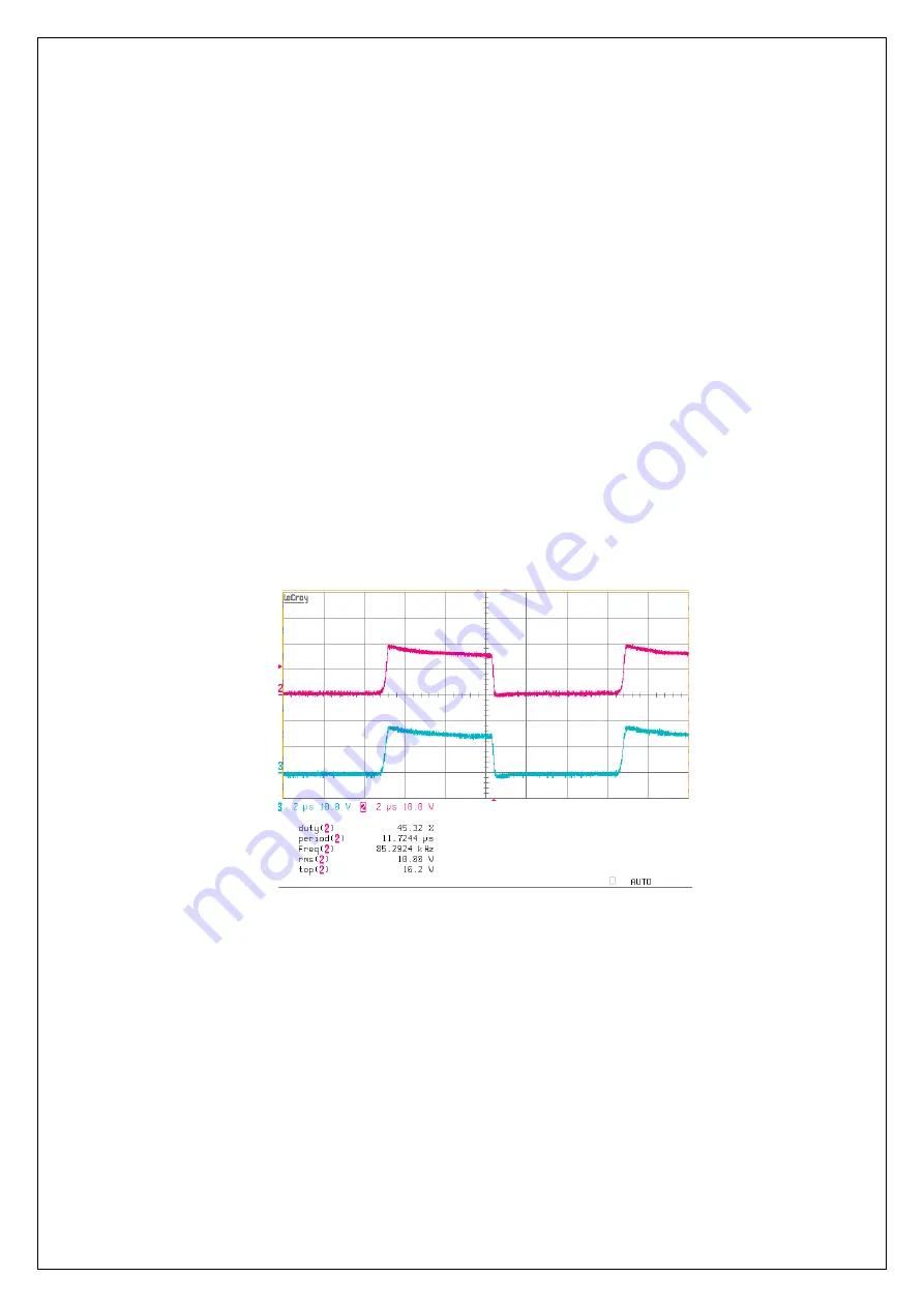
Under these conditions, the oscilloscope can be seen as follows.
7.
Two signals should be seen as 85±%5 KHz frequency. Voltage should not be spiked
in both signal fluctuating edges. Signal peaks should not be passed 18V.
8.
In third channel of oscilloscope with isolated probe, negative side of probe is
connected to number 3 of Q1; positive side is connected to number 2.
Volt/Div=200V Offset=-600 are all set. Trigger is set to channel 2 and the slope step
should be pos/time.
9.
Number 1 of J1 socket is connected to negative side of measuring device, number 2
is connected to positive side of measuring device.
10.
Positive side of the other measuring device is connected to jumper on F1; negative
side is connected to jumper on F2.
Summary of Contents for IST5 Series
Page 2: ...2 2 SERVICE MANUAL 10 15 20 30 40 60 80 100 120 160 200 300 KVA...
Page 6: ...9 9 2 PRODUCT DESCRIPTION 2 1 General View 10 15 20 30 40KVA...
Page 7: ...10 10 60 80KVA...
Page 8: ...11 11 100 120 160 200 300 KVA...
Page 13: ...16 16 2 5 Side Interior View 10 15 20 30 40KVA...
Page 16: ...19 19 2 7 Electrical Connections...
Page 35: ...38 38...
Page 36: ...39 39...
Page 51: ...54 54 30 40KVA 60 80 100 120 160 200 300 KVA...
Page 54: ...57 57...
Page 71: ...74 74 1 Turn CB2 ON 10 15 20KVA 30 40KVA...
Page 72: ...75 75 60 80 100 120KVA 2 Stop the UPS using the user front panel Main menu Control Stop...
Page 73: ...76 76 3 Turn CB1 CB3 and CB4 OFF 10 15 20KVA 30 40KVA...
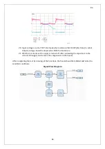
Page 100: ...103 103 Signal Flow Diagram zole trafo means isolated transformer...
Page 102: ...105 105 20 30KVA IGBT Driver 40KVA IGBT Driver...


