background image

85 


85 


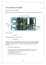
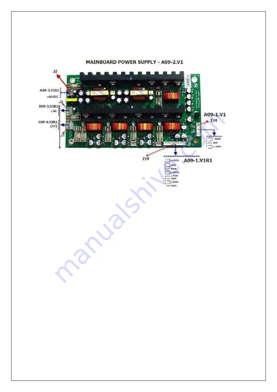
5.2 Main Board Power Supply 

This board provides 48VDC which supplies the main board and current transformers. 


Test Instruction: 


PURPOSE 
 

Board should be tested by functionality. 


EXECUTION 
 

Before the test, precaution should be performed for electrostatic protection. Without 

defined direction IPC-A-610D article 3(Protecting the Assembly-EOS/ESD and Other 
Handling Considerations) taken as a reference, ESD safety requirements should be 

provided. 


Required Test Equipments: 


Short circuit protected, constant current and voltage adjusted, series, parallel or 
individually runs and constant 5V double channel Linear DC Power Supply 


Measuring device for started conditions 


200*1,3Mp digital microscope 


3 channel isolated 1Ghz or any capable oscilloscope 


Summary of Contents for IST5 Series

Page 1: ...1 1 AEC IST5 SERIE SERVICE MANUAL 10 15 20 30 40 60 80 100 120 160 200 300 KVA 10 15 20 30 40 KVA 60 80 100 120 160 200 300 KVA...

Page 2: ...2 2 SERVICE MANUAL 10 15 20 30 40 60 80 100 120 160 200 300 KVA...

Page 3: ...d for the users of IST5 Ups Series10 15 20 30 40 60 80 100 120 160 200 300 kVA Companion Manuals For more info about this device and its options please visit www aecups com Updates Visit www aecups co...

Page 4: ...e Maintenance All servicing and maintenance is done internally All parts in the device can be serviced and replaced only by a trained technician Preventative maintenance is recommended at least once a...

Page 5: ...efore commissioning UPS and battery cabinets must be kept in the original packaging WARNING Unused batteries must be charged at regular intervals This time interval are determined by the battery suppl...

Page 6: ...9 9 2 PRODUCT DESCRIPTION 2 1 General View 10 15 20 30 40KVA...

Page 7: ...10 10 60 80KVA...

Page 8: ...11 11 100 120 160 200 300 KVA...

Page 9: ...12 12 2 2 Front View 10 15 20 30 40KVA 1 320 240 LCD DISPLAY 2 FRESH AIR GRIDS 3 EPO BUTTON 4 MENU KEYS 5 MIMIC DIAGRAM...

Page 10: ...13 13 60 80 100 120 160 200KVA 1 320 240 LCD DISPLAY 2 FRESH AIR GRIDS 3 EPO BUTTON 4 MENU KEYS 5 MIMIC DIAGRAM...

Page 11: ...NVERTER COOLING FANS 2 DC BAS RAMPING UP BUTTON 3 MAINS SWITCH 4 MAINTENANCE BYPASS SWITCH 5 BYPASS TERMINALS 6 MAIN CONNECTION TERMINALS 7 OUTPUT CONNECTORS TERMINALS 8 GROUND CONNECTION 9 BATTERY FA...

Page 12: ...NALS 4 OUTPUT CONNECTORS TERMINALS 5 GROUND CONNECTION 6 OUTPUT FUSES 7 BATTERY FAST FUSES AND CONNECTION TERMINALS 8 BATTERY START UP SWITCH 12 BARTTERY START UP SWITCHES 13 RS232 TERMINAL FOR COMMUN...

Page 13: ...16 16 2 5 Side Interior View 10 15 20 30 40KVA...

Page 14: ...CHANNEL 2 DC BAS RAMPING UP BUTTON 3 EXTERNAL BYPASS SWITCH 4 MAINTENANCE BYPASS SWITCH 5 MAINS SWITCH 6 MAINS CONNECTION TERMINALS 7 GROUND CONNECTION 8 ETERNAL BYPASS TERMINALS 9 OUTPUT CONNECTORS...

Page 15: ...AIR DISCHARGE CHANNEL 14 RS232 TERMINAL FOR COMMUNICATION SOFTWARE 15 OPTIONAL CARD SLOTS 16 OPTIONAL PARALLEL PORT TERMINAL 80 100 120 160 200 300 KVA 1 PARALLEL PORT TERMINAL 2 RECTIFIER CHARGER IN...

Page 16: ...19 19 2 7 Electrical Connections...

Page 17: ...age DC bus voltage is then converted to mains synchronized AC voltage by the inverter This is a high quality voltage Generated AC power is applied to loads through the static semi conductor switches a...

Page 18: ...ic mains bypass as phase and frequency Therefore Inverter frequency can be considered same with mains as long as it is within frequency limit User can switch between mains and inverter by using front...

Page 19: ...er unit is fed by the AC mains power Inverter and battery charge units are fed by DC supply generated by rectifier unit 2 9 2 Battery Stored Mode When the mains voltage is bad the UPS runs on battery...

Page 20: ...ke up to 15ms varying according to load type 2 9 4 Automatic Restart Mode In case of any failure of the mains UPS will continue feeding the critical loads until the batteries reaches the end of discha...

Page 21: ...rge Current Constant current at 1 10 rate of the battery capacity is applied to battery until reaches the float voltage Float Charge Depending on the battery discharge current the 1 3 of the battery e...

Page 22: ...ry test Auto Battery Test The auto battery test discharges 10 of the battery energy in a user defined period Default is 90 days Test reports the battery condition as good weak or replace Results of th...

Page 23: ...tery discharge LED Illuminates on battery mode Flashes when UPS is started up through batteries 4 Battery charge indicator LED Illuminates while the batteries are charging 5 Battery module 6 DC AC mod...

Page 24: ...guage Communication LOGGING Log Code Date Time Log Records Information MAINS Frequency Current Voltage Apparent Power Active Power Power Factor WARNINGS Actual Alarms BATTERY Voltage Current Temperatu...

Page 25: ...to the opening screen 2 11 2 Main Menu Screen To switch from opening screen to the Main menu press Enter 2 11 3Navigation through the menu Use up and down keys to move the cursor arrow Press Enter to...

Page 26: ...energy and reports batteries which has more capacity than 10 as Good less capacity than 10 as Replace according to the test results After UPS is started it makes quick battery test every 24 hours and...

Page 27: ...Active power apparent power and power factor of each phase L CF Load percent of each phase and crest factor Bypass UP I F Voltage current and frequency of each phase phase neutral Battery Mode UPS ope...

Page 28: ...Parallel battery arm number x Serial battery arm number Battery capacity adjusted in UPS 2 11 7 Setup Menu Setup menu consists of the following Date Time To set date and time use up and down keys to...

Page 29: ...efine when the device will be started after the normal values of the mains are restored Battery self test This function can be turned on to start the user independent battery tests Set the time interv...

Page 30: ...33 33 Language Set the menu language Communication Set the protocol for the RS232 connection The options are SEC and TELNET...

Page 31: ...ewing a log press enter to see detailed info about the UPS All recorded data for that particular event status setup etc can be seen on the menu Use up and down keys to see older newer event logs 2 11...

Page 32: ...be replaced Defected batteries must be uninstalled and transported to the destruction points with safety precautions taken Battery ingredients are hazardous In case of contact with battery ingredient...

Page 33: ...ut from the fans on the rear side of the device Care must be taken in order not to cover the air entrance and exit spots UPS must be positioned on a place where it is protected from water etc contact...

Page 34: ...e battery cabinet Keep battery cabinets and shelves high above the ground UPS should be protected against floods or liquid contacts Battery rooms should be properly ventilated Shelves will be accessib...

Page 35: ...38 38...

Page 36: ...39 39...

Page 37: ...A 20KVA 30KVA 40KVA BATTERIES IN SERIES 31 31 31 31 31 NUMBER OF PARALLEL ARMS 2 2 2 2 2 TOTAL NUMBER OF BATTERIES 62 62 62 62 62 I_bat_max V_bat_cut off A 16 3 24 6 32 7 49 1 49 1 RECOMMENDED INTERNA...

Page 38: ...breakers are recommended if the load is suitable 3 1 6 External Protections To protect the AC inputs thermal magnetic breakers or V type breakers must be installed on the distribution board Herein th...

Page 39: ...89 84 6 81 6 78 9 75 72 4 60 133 126 4 121 7 118 4 112 5 108 5 80 177 168 2 162 1 157 8 149 9 144 5 100 222 210 9 203 3 197 3 187 4 180 7 120 266 252 7 243 6 236 7 224 9 216 7 It should be noted that...

Page 40: ...3 1 5 3 Cable connections ATTENTION 3 pole circuit breakers switch are used for the input and output of UPS Neutral line must not be interrupted 3 1 5 3 1 for IST5 10 15 20 30 40 KVA 10 15 20KVA 30 4...

Page 41: ...teps to connect the cables properly 1 Turn OFF all the distribution board breakers both input and output distribution boards to make sure that the load and mains are completely disconnected from any c...

Page 42: ...45 45 2 Unscrew and remove the metal board on the rear side of the device 3 Connect the ground cable 10 15 20KVA 30 40KVA...

Page 43: ...these circuit breakers is explained on the operation section 5 Connect the input cables R to INPUT L1 S to INPUT L2 T to INPUT L3 N Neutral to INPUT N 6 Check the phase sequence 7 Repeat steps 4 5 for...

Page 44: ...of UPS and consider the local directions WARNING Check the grounding before starting the UPS Wrong works or grounding on UPS or other devices of installation may be hazardous Wrong works and groundin...

Page 45: ...put and output distribution boards to make sure that the load and mains are completely disconnected from any cable 2 Connect the ground cable Unscrew and remove the metal board on the rear side of the...

Page 46: ...Make sure that the circuit breakers are off The uses of these circuit breakers are explained on the operation section 4 Connect the input cables R to INPUT L1 S to INPUT L2 T to INPUT L3 N Neutral to...

Page 47: ...are galvanic isolation transformers at input of UPS and consider the local directions WARNING Check the grounding before starting the UPS Wrong works or grounding on UPS or other devices of installati...

Page 48: ...e batteries Short circuited batteries are hazardous to human health and environment Battery terminal may rise up to 450 Vdc Battery temperature monitoring Internal battery temperature is monitored by...

Page 49: ...the cable to terminals of two neutral N battery neutral one Battery and one Battery respectively 7 Connect four cables that come from UPS to terminals on battery cabinet or in battery room according...

Page 50: ...tery cabinet are given To connect to these type fuses the lowest diameter cables are suggested Please refer to standard called EN 50525 2 31 VDE 0100 430 in this subject The selection should be such t...

Page 51: ...54 54 30 40KVA 60 80 100 120 160 200 300 KVA...

Page 52: ...0 KVA Connections on the front side of UPS One RS232 serial communication connection Standard Two expansion slots Optional Connections on the top side of UPS One parallel port Standard 3 1 5 5 3 for A...

Page 53: ...ered as an option Please contact your dealer for parallel operation Parallel application should be made by authorized personal of AEC In case of need for redundancy or more power IST5 series can be op...

Page 54: ...57 57...

Page 55: ...close possible as to each other max 6 x 110 cm paralleling cables Each device must have its own ground cable UPS must be connected in parallel on the distribution panel an phases must be connected cor...

Page 56: ...59 59 3 2 1 2 30 40 KVA Connect the parallel cable as shown in figure below Only use the cables provided by AEC Software settings on the user panel should be made by authorized personnel...

Page 57: ...60 60 3 2 1 3 60 80 KVA Connect the parallel cable as shown in figure below Only use the cables provided by AEC Software settings on the user panel should be made by authorized personnel...

Page 58: ...61 61 3 2 1 4 100 120 KVA Connect the parallel cable as shown in figure below Only use the cables provided by AEC Software settings on the user panel should be made by authorized personnel...

Page 59: ...as close to each other as possible The distance between must not exceed 1 meters 3 2 2 3 Making the electrical connections 1 Make sure that the devices are turned OFF and have been kept off for at lea...

Page 60: ...or each device Do NOT use the same set of batteries on more than one device at the same time 9 Connect the communication cable and secure the connections 10 Check the termination resistors on the conn...

Page 61: ...lel Operation screen Main screen Setup Service Menu Parallel Operation 2 Change MODE to parallel using the menu keys 3 Set a different ID number for each device and then authorize one of the devices a...

Page 62: ...3 2 3 1 Parallel start up Read the following to start the parallel system Turn on the UPS breakers on the distribution board and then turn on the main input breaker Start one of the UPS using the fro...

Page 63: ...the devices to online mode select switch to UPS on any device 3 2 3 3 Stopping Removing a single UPS In a parallel Challenger system any one of the devices can be removed off the system without affect...

Page 64: ...breaker CB3 and the maintenance breaker CB2 Turn off the UPS breakers on the distribution board 3 2 3 4 Stopping all UPS To stop all the UPS in a parallel system go to Setup Service Menu Control Stop...

Page 65: ...ce purposed switching is done properly If UPS is active while it is working thanks to auxiliary short circuit info located in CB3 mains makes the bypass static switches active The system will be switc...

Page 66: ...between each step 1 Turn all circuit breakers OFF 2 Push the soft start button SW1 at least for 10 sec 3 Turn input circuit breaker CB1 ON If there is an external bypass input put the external bypass...

Page 67: ...70 70 60 80 100 120KVA 4 Start the UPS using the front panel Main menu Control Password Start 5 Check the UPS has switched to normal operation mode via mimic diagram LEDs and LCD panel...

Page 68: ...71 71 6 Turn battery circuit braker CB4 ON 7 Turn output circuit braker CB3 ON 10 15 20 KVA 30 40 KVA...

Page 69: ...des Testing After first start up check device operation by switching between the operations Modes change manually 4 1 3 1 Switching from Online Mode to Battery Mode Turn CB1 OFF This action cuts off t...

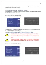
Page 70: ...not switch to normal mode if the inverter voltage is out of limits or there is an over load or over temperature situation 4 1 3 4 Switching from Online Mode to Maintenance Bypass Mode WARNING Make su...

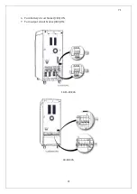
Page 71: ...74 74 1 Turn CB2 ON 10 15 20KVA 30 40KVA...

Page 72: ...75 75 60 80 100 120KVA 2 Stop the UPS using the user front panel Main menu Control Stop...

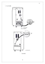
Page 73: ...76 76 3 Turn CB1 CB3 and CB4 OFF 10 15 20KVA 30 40KVA...

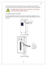
Page 74: ...5 minutes before opening up the device after it is completely turned off for safety 4 1 4 Performing a Complete Shutdown 1 Turn off the loads connected to the device 2 Use the front panel to turn the...

Page 75: ...B1 WARNING Make sure that there are no critical loads on the UPS output before performing a complete shutdown 4 1 5 EPO Emergency Power OFF By pressing the EPO button the device respectively turns the...

Page 76: ...gation IST5 series has an RS 232 interface which supports SEC and TELNET protocol as standard This interface is fully isolated and safe UPS can be monitored remotely via a computer PC or SNMP by using...

Page 77: ...fined direction IPC A 610D article 3 Protecting the Assembly EOS ESD and Other Handling Considerations taken as a reference ESD safety requirements should be provided Required Test Equipments Short ci...

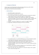
Page 78: ...l set Trigger is set to channel 2 and the slope step should be pos time 5 Number 1 of J4 socket is applied to zero number 2 is applied to 15VDC 6 Under these conditions the oscilloscope can be seen as...

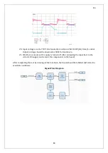
Page 79: ...ble signals in the channel 1 can be seen as increased gradually in the following picture 13 If incoming voltage is 250V output voltage 48V is regulated and signal changes can be observed during the re...

Page 80: ...d not pass 600V 17 15V supply should be from J4 socket 18 0 900VDC supply is increased by 50V Once it reaches 250VDC output voltage should be 27VDC 2 input should not be passes 200Ua from DC supply an...

Page 81: ...be observed as 48V 2 and above 21 Wait for a moment as DC supply is turned off After unloading the capacitors in the circuits DC supply and remove the components in the board After completing the test...

Page 82: ...ut defined direction IPC A 610D article 3 Protecting the Assembly EOS ESD and Other Handling Considerations taken as a reference ESD safety requirements should be provided Required Test Equipments Sho...

Page 83: ...the ground of measuring device number 1 is the active point of the measuring device Number 2 of F8 fuse is applied to 24VDC from the 0 24V point of power supply Approximately 20mA is withdrawn and D1...

Page 84: ...dure D22 LED is ON Number 3 4 of J59 is measured as ground of measuring device number 6 7 is measured as active point of the device DC 12V 2 is measured 24 If number 3 4 and number 6 7 of J59 socket a...

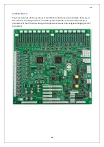
Page 85: ...ions of the UPS Not only the basic function like start stop it also monitors the changes that occur in UPS operational modes evaluation of the sampled parameters of the UPS and according to that produ...

Page 86: ...ction Without defined direction IPC A 610D article 3 Protecting the Assembly EOS ESD and Other Handling Considerations taken as a reference ESD safety requirements should be provided Required Test Equ...

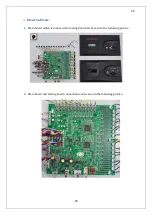
Page 87: ...90 90 Electrical Tests 1 Main board which is connected to testing board can be seen in the following picture 2 Main board and testing board connections can be seen in the following picture...

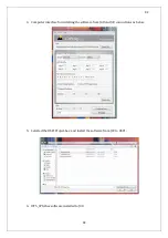
Page 88: ...91 91 3 Should install the testing software for testing the main board Program is downloaded via J48 j49 and DSP1 DSP2 connections J20 and J21 jumpers should connect for install the software...

Page 89: ...2 4 Computer interface for installing the software from J48 and J49 connections as below 5 Selected the DSP1Project hex and install the software from J49 to DSP1 6 IST5_CPId hex software installed to...

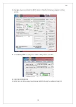
Page 90: ...off the energy and take out J20 J21 jumpers and then energised again Should seen the flashing of D56 LED 8 Cut off the energy again then connect J20 J21 jumper 9 Emulator is connected to J32 as follow...

Page 91: ...he DSP2 software from the following computer interface picture 11 Select IST5_CPId hex via Open Code File and Open Password File 12 Click the ERASE FLASH 13 After that cut off the energy and then inst...

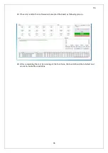
Page 92: ...1 jumper 15 Energised the circuit and open the following computer interface 16 Chose serial connection values as following picture 17 Read the main boards barcode and chose boards type In that way com...

Page 93: ...19 If board is reliable than software will accepted the board as following picture 20 After completing the test by running all the functions the board should be labelled and stored in available condi...

Page 94: ...is controlled by the main board This is the board that drives by pass thyristor and by pass inverter thyristor By pass voltage and current and also inverter voltage and current readings can be done by...

Page 95: ...hannel isolated 1Ghz or any capable oscilloscope Adjusted DUTY ratio function generator Thermal camera preferably able to transfer image to the computers Preparation before the Test Required thyristor...

Page 96: ...side 4 The feeding voltage is applies as follows pin 4 5 of J38 socket is connected to 12V pin 6 7 is connected to GND 5 Number 3 of U2 regulator integration should be measured as 12V against GND 6 Nu...

Page 97: ...J3 and J4 Pin 1 of sockets are negative and pin 2 of sockets are positive Probes of the oscilloscope should be polarized according to this statement See Picture 4 Picture 4 13 Thyristor J9 and J10 co...

Page 98: ...signals should be measured in the order of J11 and J23 Pin 1 of sockets are negative and pin 2 of sockets are positive Probes of the oscilloscope should be polarized according to this statement See Pi...

Page 99: ...e signal should be seen in the number 10 of the U3 integration against GND See Picture 2 41 The signal should be seen in the number 2 of Q16 transistor as above against GND See Picture 3 42 The signal...

Page 100: ...103 103 Signal Flow Diagram zole trafo means isolated transformer...

Page 101: ...fast monitoring and control is provided This is accomplished by IGBT control logic available inside the hybrids over this board In this part the transistor s collector emitter voltage is continuously...

Page 102: ...105 105 20 30KVA IGBT Driver 40KVA IGBT Driver...

Page 103: ...ed direction IPC A 610D article 3 Protecting the Assembly EOS ESD and Other Handling Considerations taken as a reference ESD safety requirements should be provided Required Test Equipments Short circu...

Page 104: ...ld be adjusted separately First channel is set to 15Vdc and 500mA 2 Output of function generator should be set by 16 kHz 50 Duty and able to produce square wave signal Adjusted signal should start fro...

Page 105: ...2 V1 board should be assembled into C09 1 V4 and not be affected from vibration by strengthening the connection 6 PWM signals and feeding voltage in the Table 1 should be applied to the C09 1 V4 board...

Page 106: ...ainst GND High 13 Pin 3 of the U7 integration should be 15 5Vdc pin 2 should be observed as 19Vdc against GND Low 14 Pin 3 of the U9 integration should be 11 5Vdc pin 2 should be observed as 8Vdc agai...

Page 107: ...15V 15V 14 2V 12V 0V 0V 0 1 0 Giri Voltaj k On Off Durumu After completing the test by running all the functions the board should be labeled and stored in available conditions GND AREAS Signal Flow D...

Page 108: ...be provided Required Test Equipments Short circuit protected constant current and voltage adjusted series parallel or individually runs and constant 5V double channel Linear DC Power Supply Measuring...

Page 109: ...be provided Required Test Equipments Short circuit protected constant current and voltage adjusted series parallel or individually runs and constant 5V double channel Linear DC Power Supply Measuring...

Page 110: ...should be provided Required Test Equipments Short circuit protected constant current and voltage adjusted series parallel or individually runs and constant 5V double channel Linear DC Power Supply Mea...

Page 111: ...hould be provided Required Test Equipments Short circuit protected constant current and voltage adjusted series parallel or individually runs and constant 5V double channel Linear DC Power Supply Meas...

Page 112: ...ould be provided Required Test Equipments Short circuit protected constant current and voltage adjusted series parallel or individually runs and constant 5V double channel Linear DC Power Supply Measu...

Page 113: ...uld be provided Required Test Equipments Short circuit protected constant current and voltage adjusted series parallel or individually runs and constant 5V double channel Linear DC Power Supply Measur...

Page 114: ...be provided Required Test Equipments Short circuit protected constant current and voltage adjusted series parallel or individually runs and constant 5V double channel Linear DC Power Supply Measuring...

Page 115: ...d be provided Required Test Equipments Short circuit protected constant current and voltage adjusted series parallel or individually runs and constant 5V double channel Linear DC Power Supply Measurin...

Page 116: ...sockets of J36 J37 will be unplugged on the main board as shown in Picture 2 3 Plug the serial cable into the RS232 slot on the rear side of the UPS The J1 inverter cable socket which comes from DB9 s...

Page 117: ...123 123 Picture 04 Picture 05 6 Check the DSP version no it can be either 332 or 335 For example F28335PGFA...

Page 118: ...r the software update There are two methods for energising main board at Boxer model External power supply is the first method for energising The second method is to unplug all NH fuses The best fit m...

Page 119: ...quipment for the external power supply Picture 09 12 To ensure safe operation do pay attention to DC bus voltage after NH fuses were unplugged When the input breaker CB1 was turned on the mainboard en...

Page 120: ...in the control panel This shows that the programming is successfully done 17 Turn UPS s input breaker CB1 off Plug in J2 sockets instead of external power supply Plug in input and battery fuses if th...

Page 121: ...left side slot on the rear side of the machine 1 Unscrew and remove the left hand side slot cover reach the female CAN socket attached to the slot cover 2 Detach the cable from the socket cover using...

Page 122: ...able 4 Insert the signal cables into the sockets while pressing on the connector with a screwdriver Operation Relay outputs are isolated from the UPS and ground If the contacts are going to be used fo...

Page 123: ...urrent NO 10A Max Switching Current NC 3A Max Switching Voltage NO 250VAC 110VDC Max Switching Voltage NC 250VAC 110VDC Cable Cross section min 0 25mm max 0 5mm Isolated input info Min Input Voltage 3...

Page 124: ...24 Output 5 battery fault COM 12 Output 1 low battery COM 25 Output 5 battery fault NC 13 Output 1 low battery NC Pins 11 25 belong to output relays and their default function is shown on the table Di...

Page 125: ...ion examples Output relays can be connected in various ways to meet with control necessities AND and OR configurations can be set with the relays by connecting them in series or parallel as seen in th...

Page 126: ...d at overload more than time limit adjusted The Loads will be transferred to bypass line 11 End of Battery Test Battery test has completed You can see the all results via front panel status menu 12 Ba...

Page 127: ...d and temperature values are normal UPS will switch to normal mode 33 Charger Nor Temp Charger booster module temperature is in the allowed limits charging will be activated again 34 STS Nor Temp Temp...

Page 128: ...nergized through bypass line 60 Maint Bypass Mode UPS is operating in the maintenance bypass mode load are energized through maintenance bypass line 61 Parallel Mode 2 or more UPS are operating in pow...

Page 129: ...ication between the systems is not available 85 STS OverCurrent OverCurrent in Bypass line 86 BYP Phase Rot Err Reverse phase sequence was detected in mains at the UPS run time 87 Output DC Volt Fault...

Reviews: