95
95
14.
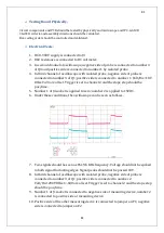
J48 and J49 connected each other and take out the J21 jumper.
15.
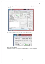
Energised the circuit and open the following computer interface.
16.
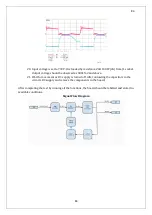
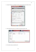
Chose serial connection values as following picture.
17.
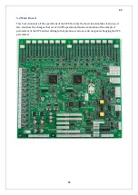
Read the main boards barcode and chose boards type. In that way completed main board
pre test procedure.
18.
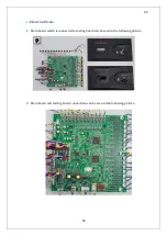
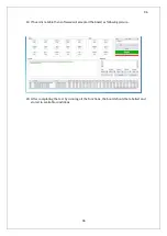
Start the board test
Summary of Contents for IST5 Series
Page 2: ...2 2 SERVICE MANUAL 10 15 20 30 40 60 80 100 120 160 200 300 KVA...
Page 6: ...9 9 2 PRODUCT DESCRIPTION 2 1 General View 10 15 20 30 40KVA...
Page 7: ...10 10 60 80KVA...
Page 8: ...11 11 100 120 160 200 300 KVA...
Page 13: ...16 16 2 5 Side Interior View 10 15 20 30 40KVA...
Page 16: ...19 19 2 7 Electrical Connections...
Page 35: ...38 38...
Page 36: ...39 39...
Page 51: ...54 54 30 40KVA 60 80 100 120 160 200 300 KVA...
Page 54: ...57 57...
Page 71: ...74 74 1 Turn CB2 ON 10 15 20KVA 30 40KVA...
Page 72: ...75 75 60 80 100 120KVA 2 Stop the UPS using the user front panel Main menu Control Stop...
Page 73: ...76 76 3 Turn CB1 CB3 and CB4 OFF 10 15 20KVA 30 40KVA...
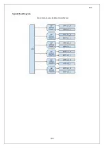
Page 100: ...103 103 Signal Flow Diagram zole trafo means isolated transformer...
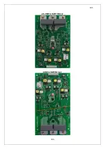
Page 102: ...105 105 20 30KVA IGBT Driver 40KVA IGBT Driver...

