Operations
34
IST5 Tower UPS 10kVA~40kVA User Manual
5. Operations
5.1 UPS Start-up
5.1.1 Start from Normal Mode
The UPS must be started up by commissioning engineer after the completeness of
installation. The steps below must be followed
:
Ensure all the circuit breakers are open.
Close the output circuit breaker (CB) and then the input CB and the
system starts initializing. If the system has dual inputs, close both of the breakers.
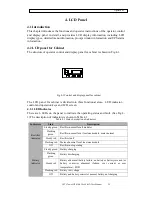
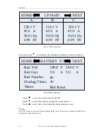
The LCD in front of the cabinet is lit up. The system enters the home
page, as shown in Fig.4-2.
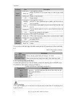
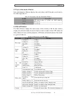
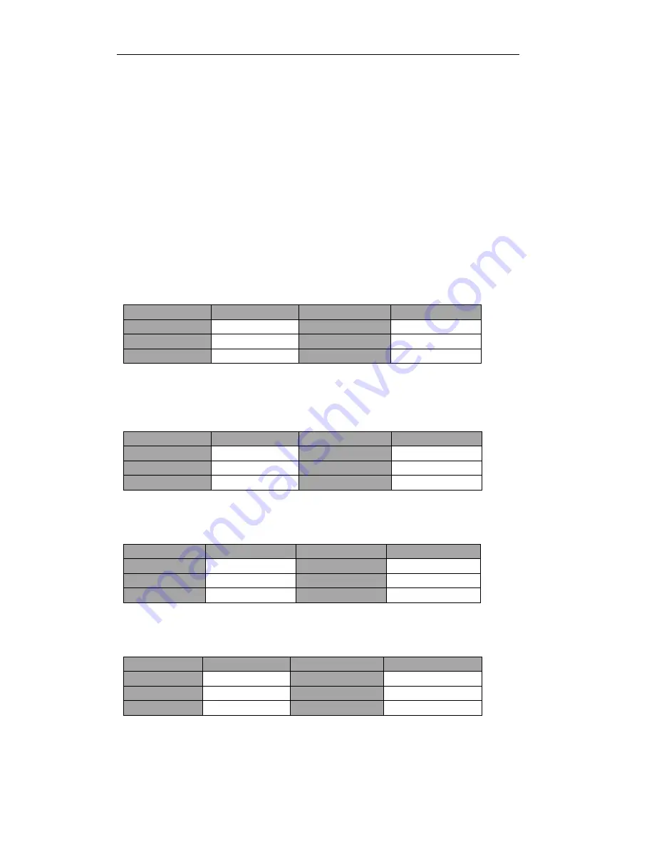
Notice the energy bar in the home page, and pay attention to the LED
indicators. The rectifier flashes indicating the rectifier is starting up. The LED
indicators are listed below in Table 5.1.
Table 5.1 Rectifier starting up
Indicator
Status
Indicator
Status
Rectifier
green flashing
Inverter
off
Battery
red
Load
off
Bypass
off
Status
red
After 30S, the rectifier indicator goes steady green, presenting the
finishing of rectification and bypass static switch closes then the inverter is starting
up. The LED indicators are listed below in Table.5.2.
Table 5.2 Inverter starting up
Indicator
Status
Indicator
Status
Rectifier
green
Inverter
green flashing
Battery
red
Load
green
Bypass
green
Status
red
The UPS transfers from the bypass to inverter after the inverter goes
normal. The LED indicators are listed below in Table 5.3.
Table 5.3 Supplying the load
Indicator
Status
Indicator
Status
Rectifier
green
Inverter
green
Battery
red
Load
green
Bypass
off
Status
red
The UPS is in Normal Mode. Close the battery circuit breakers and the
UPS starts charging the battery. The LED indicators are listed below in Table 5.4.
Table 5.4 Normal mode
Indicator
Status
Indicator
Status
Rectifier
green
Inverter
green
Battery
green
Load
green
Bypass
off
Status
green
The starting up done.
Summary of Contents for IST5010
Page 4: ......

