background image


IST5 Tower UPS 10kVA~40kVA User Manual            37 

Operations 

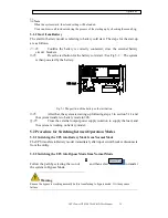
5.2.5 Switching the UPS into Normal Mode from Maintenance Bypass Mode 

These following procedures can transfer the load from the Maintenance Bypass mode 
to inverter output. 




After finish of maintenance, close the bypass breaker and the bypass static switch 

will be turned on in  30S after the  LED screen  goes on, the bypass  indicator goes 
green and the load is powered through maintenance bypass and static bypass.  




Turn off the maintenance bypass switch and fix the protection cover, and then the 

load is powered through bypass. The rectifier starts followed by the inverter.  




After 60S, the system transfers to Normal mode. 


Waring


The system will stay on bypass mode until the cover of maintenance bypass breaker is fix. 


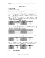
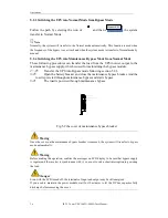
5.3 Battery Maintenance


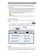
If the battery is not discharged for a long time, it is necessary to test the condition of 
the battery.  

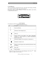
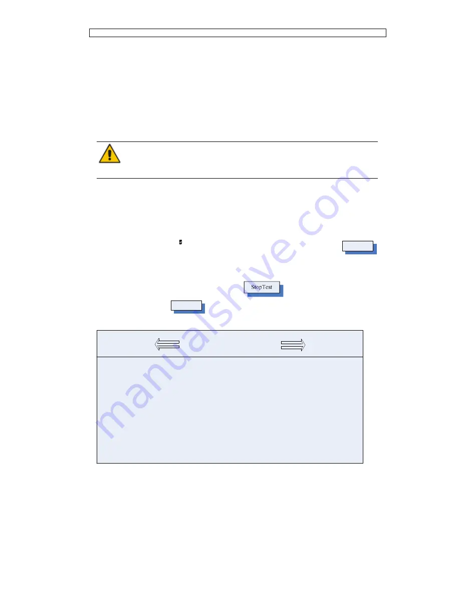
Enter the menu


as is shown in Fig.5-3 and select the icon 

MaintTest

the  system  transfers  into  the  Battery  mode  for  discharging.  The  system  will 

discharge the batteries until the alarm of “Battery low voltage” is given Users can 

stop the discharging by the “Stop Test” icon

With the icon of 

BattTest

, batteries will be discharged for about 30 seconds, 

and then re-transfer to normal mode.


FUNCTION

END

BACK

Manual INV

ManualByp/Esc

Fault Clear

Stop Test

Batt. Test

Maint Test


 Fig.5.3 Battery maintenance 

5.4 EPO


The EPO button located in the operator control and display panel (with cover to avoid 
disoperation, see Fig.5-5) is designed to switch off the UPS in emergency conditions 
(e.g., fire, flood, etc.).To achieve this, just press the

 EPO

 button, and the system will 

Summary of Contents for IST5010

Page 1: ...al Support Engineer Maintenance Engineer Note Our company is providing a full range of technical support and services Customer can contact our local office or customer service center for help The manu...

Page 2: ...to restart Mode 8 2 3 7 Frequency Converter Mode 8 2 4 UPS Structure 8 2 4 1 UPS Configuration 8 2 4 2 UPS Outlook 8 3 Installation Instruction 13 3 1 Location 13 3 1 1 Installation Environment 13 3 1...

Page 3: ...o Maintenance Bypass Mode from Normal Mode 41 5 2 5 Switching the UPS into Normal Mode from Maintenance Bypass Mode 42 5 3 Battery Maintenance 42 5 4 EPO 42 5 5 Installation of Parallel Operation Syst...

Page 4: ......
Page 5: ...uipment Warning Label The warning label indicates the possibility of human injury or equipment damage and advises the proper step to avoid the danger In this manual there are three types of warning la...

Page 6: ...ong time storing of UPS Maintenance Replacement Danger All the equipment maintenance and servicing procedures involving internal access need special tools and should be carried out only by trained per...

Page 7: ...worn to prevent injury from accidental electrical arcs Only use tools e g wrench with insulated handles The batteries are very heavy Please handle and lift the battery with proper method to prevent a...

Page 8: ...ad Battery Bypass Input Output Switch Rectifier Discharger Charger Inverter Fig 2 1 UPS Configuration 2 3 Operation Mode The Modular UPS is an on line double conversion UPS that permits operation in t...

Page 9: ...e operation diagram Note With the function of Battery cold start the UPS may start without utility See more detail in section 5 1 2 2 3 3 Bypass Mode If the inverter overload capacity is exceeded unde...

Page 10: ...available e g during a maintenance procedure See Fig 2 5 Main Input Manual Bypass Battery Bypass Input Output Switch Rectifier Discharger Inverter Charger Load Fig 2 5 Maintenance mode operation diagr...

Page 11: ...e programmed to System Auto Start Mode after EOD The system starts after a delay time when the AC mains recovers The mode and the delay time are programmed by the commissioning engineer 2 3 7 Frequenc...

Page 12: ...ction terminal Output CB Main input CB Bypass Input CB Maintenance CB Battery Cold Start SNMP Fig 2 11 10 15 kVA back appearance SNMP Dry Contact Parallel board Main input CB Connection terminals 232...

Page 13: ...d Dry contact Bypass Input CB Input CB Air vent Connection terminals Cold start Output CB Maintenance switch Fig 2 13 40kVA back appearance Note The Standard product is configured with single input th...

Page 14: ...ery capacity The battery will generate a little amount of hydrogen and oxygen at the end of charging ensure the fresh air volume of the battery installation environment must meet EN50272 2001 requirem...

Page 15: ...kVA 30kVA Standard Backup Type 88kg No Batteries Included 20kVA 30kVA Long Backup Type 50kg 40kVA Long Backup Type 61kg 3 2 Unloading and Unpacking 3 2 1 Moving and Unpacking of the Cabinet The steps...

Page 16: ...Installation Instruction 12 IST5 Tower UPS 10kVA 40kVA User Manual Fig 3 6 Disassemble the case 4 Remove the protective foam around the cabinet Fig 3 7 Remove the protective foam...

Page 17: ...inet to the installation position Attention Be careful while removing to avoid scratching the equipment Attention The waste materials of unpacking should be disposed to meet the demand for environment...

Page 18: ...d and immovable 6 Positioning done Attention Auxiliary equipment is needed when the mounting floor is not solid enough to support the cabinet which helps distribute the weight over a larger area For i...

Page 19: ...10 Cable entry 3 6 Power Cables 3 6 1 Specifications The UPS power cables are recommended in Table 3 2 Table 3 2 Recommended cables for power cables Contents 10 15kVA 20 30kVA 40kVA Main Input Main In...

Page 20: ...listed above when the predominant load is non linear 3 6 2 Specifications for Power Cables Terminal Specifications for power cables connector are listed as Table 3 3 Table 3 3 Requirements for power m...

Page 21: ...erminal battery terminal and protective earth terminal are shown in Fig 3 11 Fig 3 13 Fig 3 11 connections terminals for 10 15kVA Fig 3 12 connections terminals for 20 30kVA Fig 3 13 connections termi...

Page 22: ...ntrol and Communication Cables The front panel of the bypass module provides dry contact interface J2 J11 and communication interface RS232 RS485 SNMP Intelligent card interface and USB port as it is...

Page 23: ...tion is settable Default Low battery alarming J8 2 BAT_LOW_ALARM_NO Output dry contact Normally open function is settable Default Low battery alarming J8 3 BAT_LOW_ALARM_GND Common terminal for J8 1 a...

Page 24: ...M common terminal J3 1 ENV_TEMP Detection of environmental temperature J3 2 TEMP_COM common terminal Note Specified temperature sensor is required for temperature detection R25 5Kohm B25 50 3275 pleas...

Page 25: ...em The interface diagram is shown in Fig 3 16 and interface description is shown in Table 3 8 J5 GEN 24V AUX N O AUX N O Generator Fig 3 16 Diagram of status interface and connection of generator Tabl...

Page 26: ...will be activated via the isolation of a relay The interface diagram is shown in Fig 3 17 and description is shown in Table 3 10 Fig 3 18 Battery warning dry contact interface diagram Table3 10 Batte...

Page 27: ...0 is the output dry contact interface for utility failure warning when the utility fails the system will send a utility failure warning information and provide an auxiliary dry contact signal via the...

Page 28: ...on Interface RS232 RS485 and USB port Provide serial data which can be used for commissioning and maintenance by authorized engineers or can be used for networking or integrated monitoring system in t...

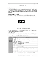
Page 29: ...CD screen 4 2 1 LED Indicator There are 6 LEDs on the panel to indicate the operating status and fault See Fig 4 1 The description of indicators is shown in Table 4 1 Table 4 1 Status description of i...

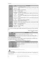
Page 30: ...no power supply Flashing red Overload output of UPS Off No output of UPS Status indicator Steady green Normal operation Steady red Failure There are two different types of audible alarm during UPS op...

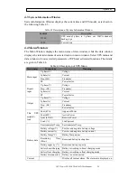
Page 31: ...in Table 4 4 Table 4 4 Description of LCD Icons Icon Description Power On Off button Parameters of Main Bypass Input History log Function set Fault Clear Battery Test Battery Maintenance language set...

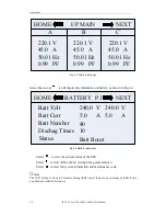
Page 32: ...shown in Fig 4 4 BATTERY P 1 Batt Boost Dischag Times 10 40 NEXT HOME Batt Number Status Batt Volt 5 0 A Batt Curr 240 0 V 240 0 V 5 0 A Fig 4 4 Battery Information Select to view the current status...

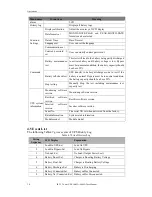
Page 33: ...aning Main input V phase V Voltage I phase A Current Freq Hz Frequency PF Power factor Bypass input V phase V Voltage Freq Hz Frequency I phase A Current PF Power factor Output V phase V Voltage I pha...

Page 34: ...condition the battery capacity should be above 25 Stop testing Manually Stop the test including maintenance test capacity test UPS system information Monitoring software version Monitoring software v...

Page 35: ...Over load 25 Bypass Overload Clear Incident above disappears 26 Bypass Overload Tout Set Bypass Over Load Timeout 27 Byp Overload Tout Clear Incident above disappears 28 Byp Freq Over Track Set Bypas...

Page 36: ...Transfer Byp Set Cancel to bypass manually 62 Esc Manual Bypass Set Escape transfer to bypass manually command 63 Battery Volt Low Set Battery Voltage Low 64 Battery Volt Low Clear Incident above dis...

Page 37: ...lance 92 Input Curr Unbalance Clear Incident above disappears 93 DC Bus Over Volt Set DC bus over Voltage 94 DC Bus Over Volt Clear Incident above disappears 95 REC Soft Start Fail Set Rectifier soft...

Page 38: ...lashing Inverter off Battery red Load off Bypass off Status red After 30S the rectifier indicator goes steady green presenting the finishing of rectification and bypass static switch closes then the i...

Page 39: ...of the battery cold start button After that the system is starting up following steps 3 in section 5 1 1 and the system transfers to battery mode in 30S Close the external output power supply isolati...

Page 40: ...section 5 2 2 Open the battery breaker and close the maintenance bypass breaker And the load is powered through maintenance bypass and static bypass The load is powered through maintenance bypass Pro...

Page 41: ...over of maintenance bypass breaker is fix 5 3 Battery Maintenance If the battery is not discharged for a long time it is necessary to test the condition of the battery Enter the menu as is shown in Fi...

Page 42: ...he UPS control circuit will remain active however the output will be turned off To completely isolate the UPS users need to open the external mains input supply to the UPS Warning When the EPO is trig...

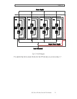
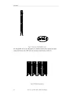
Page 43: ...10kVA 40kVA User Manual 39 Operations UPS1 Load Connected Output Power Supply Power Supply UPS2 UPS3 UPS4 Fig 5 6 Parallel diagram The parallel board is located at the back of the UPS cabinet as is sh...

Page 44: ...40kVA User Manual A Fig 5 7 Location of the Parallel board All the parallel cables are designed to be shielded and double insulated and are connected between the UPS to form a loop as shown below in F...

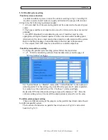
Page 45: ...High Leakage Current Warning in the first part of this manual 4 The outputs of all UPS must be connected to a common output bus Parallel system software setting To change the parallel system setting...

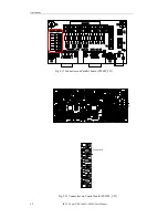
Page 46: ...0kVA 40kVA User Manual Fig 5 11 Connectors on Parallel board PS1409_TF1 INV REC INV REC 2 1 26 25 2 1 25 26 19 20 2 1 1 2 33 34 19 20 2 1 15 1 2 16 19 20 2 1 Zoominjumperconnnectors Fig 5 12 Connector...

Page 47: ...lel keep all the connectors J21 J25 open As is shown in Fig 5 12 Note The connectors not mentioned keep them untouched When all the connection and settings are finished follow the steps below for the...

Page 48: ...ry according to requirements battery life can be prolonged The battery life is mainly determined by the following factors 1 Installation The battery should be placed in dry and cool place with good ve...

Page 49: ...hazardous waste and waste batteries or other standards According to the national laws the waste lead acid battery should be recycled and reused and it is prohibited to dispose of the batteries in oth...

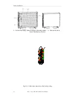
Page 50: ...ery cable according to the series number 4 Recover the cover Fig 6 1 Installation of battery 1 2 3 4 5 7 8 9 10 11 12 13 14 15 16 17 18 19 20 21 22 23 24 25 26 27 28 29 30 31 32 33 34 35 36 37 38 39 4...

Page 51: ...cable labeled L1 and the negative of battery 40 is connected to CB4 6 via the cable labeled L2 as shown in Fig 6 2 L4 L4 1 2 3 4 40 39 38 37 36 L1 5 Fig 6 2 2 Cable connection of Lay 1 Layer 2 The pos...

Page 52: ...4 as shown in Fig 6 4 L4 L4 11 30 29 28 27 26 12 13 14 15 L4 L4 Fig 6 2 4 Cable connection of Lay 3 Layer 4 The positive of the battery 16 is connected to the negative of battery 15 via the cable labe...

Page 53: ...Manual 49 Safety Precautions Fig 6 2 5 Cable connection of Lay 4 Warning Make sure the polarity of the battery is correct according to the diagrams above Test and confirm the battery voltage before c...

Page 54: ...cifying the performance and test requirements of UPS EN50091 3 IEC62040 3 AS 62040 3 VFI SS 111 Note The above mentioned product standards incorporate relevant compliance clauses with generic IEC and...

Page 55: ...vel IEC 60529 N A IP20 7 4 Electrical Characteristics 7 4 1 Electrical Characteristics Input Rectifier Table 7 5 Rectifier AC input Mains Item Unit Parameter Grid System 3 Phases Neutral Ground Rated...

Page 56: ...ischarge current EOD voltage changes linearly within the set range according to discharge current Battery Charge V cell 2 4V cell selectable from 2 3V cell 2 45V cell Constant current and constant vol...

Page 57: ...en bypass and inverter ms Synchronized transfer 0ms Bypass voltage range Settable default 20 15 Upper limit 10 15 20 25 Lower limit 10 15 20 30 40 Bypass frequency range Hz Settable 1Hz 3Hz 5Hz Synchr...

Reviews: