Installation Instruction
4 IST5 Tower UPS 10kVA~40kVA User Manual
2. Product Introduction
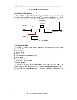
2.1 System Configuration
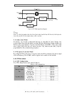
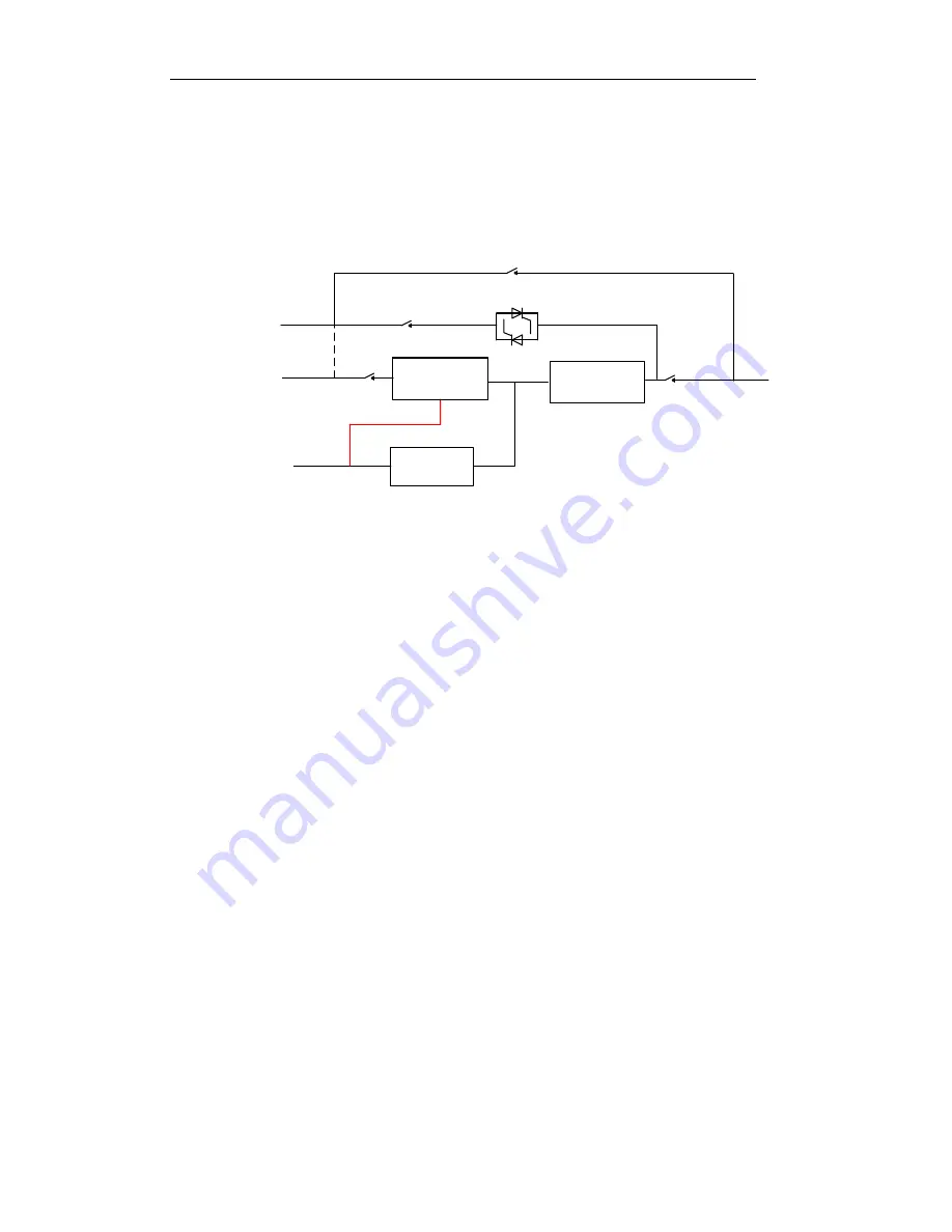
The Tower UPS is configured by the following part: Rectifier, Charger, Inverter, Static
Switch and Manual Bypass Switch. One or several battery strings should be installed to
provide backup energy once the utility fails. The UPS structure is shown in Fig. 2-1.
Main Input
Static Switch
Manual Bypass
Load
Battery
Bypass Input
Output Switch
Rectifier/
Discharger
Charger
Inverter
Fig. 2-1 UPS Configuration
2.3 Operation Mode
The Modular UPS is an on-line, double-conversion UPS that permits operation in the
following modes:
Normal mode
Battery mode
Bypass mode
Maintenance mode (manual bypass)
ECO mode
Auto-restart mode
Frequency Converter mode
2.3.1 Normal Mode
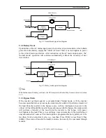
The inverter of power modules continuously supply the critical AC load. The
rectifier/charger derives power from the AC mains input source and supplies DC power
to the inverter while simultaneously FLOAT or BOOST charging its associated backup
battery.
Summary of Contents for IST5010
Page 4: ......


