Operator Control and Display Panel
42
UPS 30-300kVA User Manual
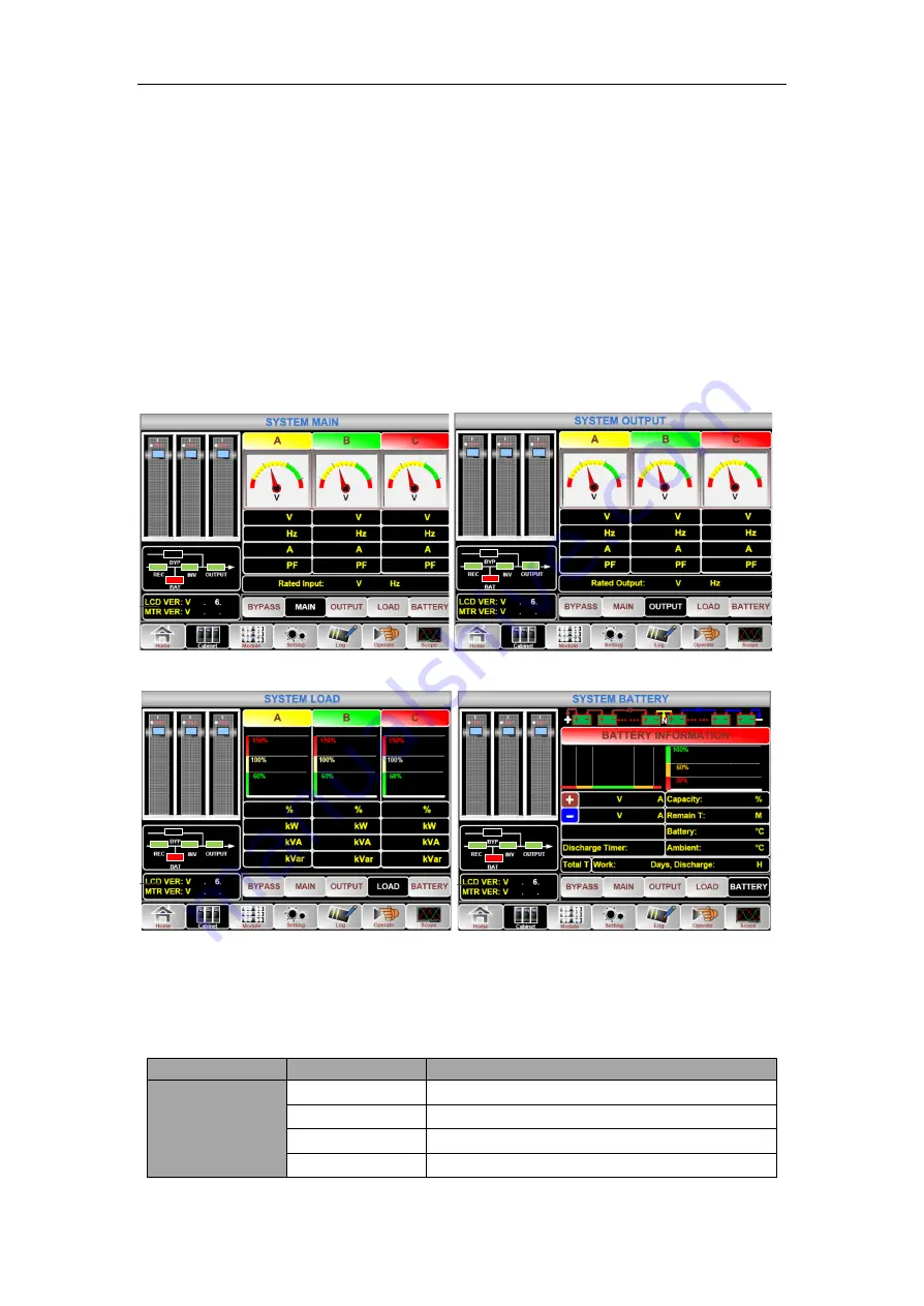
The Cabinet comprises sectors of title, information display, version running status, information
display and submenu. The sectors are described as follows.
�
Title
Display the information of the selected submenu.
�
Running status
The squares shown on the mini current path represent the various UPS power paths and show the
current UPS operating status. (The green square indicating the block working normally, the white
indicating the absent of the block and red indicating the absence of the block or in fault).
�
Version Information
The version information for LCD of the cabinet and monitor.
�
Submenu
It includes the submenu of Bypass, Main, Output, load and battery.
�
Information display
Display information of each submenu.
The interface of each submenu is shown in Figure3-5.
0
50
10
0
18
0
26
0
30
0
0
50
10
0
18
0
26
0
30
0
0
50
10
0
18
0
30
0
123.5
124.6
125.3
49.99
49.99
49.99
0.0
0.0
0.0
0.00
0.00
0.00
50
57
55
0
513
0
220
0
50
26
0
30
0
0
50
26
0
30
0
0
50
30
0
120.0
120.2
120.3
49.99
49.99
49.99
0.0
0.0
0.0
0.00
0.00
0.00
50
57
55
0
513
0
220
c
(a) Interface of Main
(b) Interface of Output
5.0
6.0
2.5
0.0
0.0
0.0
0.5
0.6
0.2
57
55
0
513
0
0.6
0.4
0.2
57
55
0
513
0
0.0
0.0
0.0
0.0
22
0.0
0.0
0.0
0.0
25.0
25.0
(d) Interface of Load
(d) Interface of Battery
Figure 3-5 Submenu interface of Cabinet
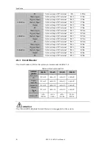
The submenu of Cabinet is described in details below in Table 3-4.
Table 3-4 Description of each submenu of Cabinet
Submenu Name
Contents
Meaning
Main
V
Phase voltage
A
Phase current
Hz
Input frequency
PF
Power factor


