UPS IST7 Series (60K-200K)
User Manual
3 Installation
61
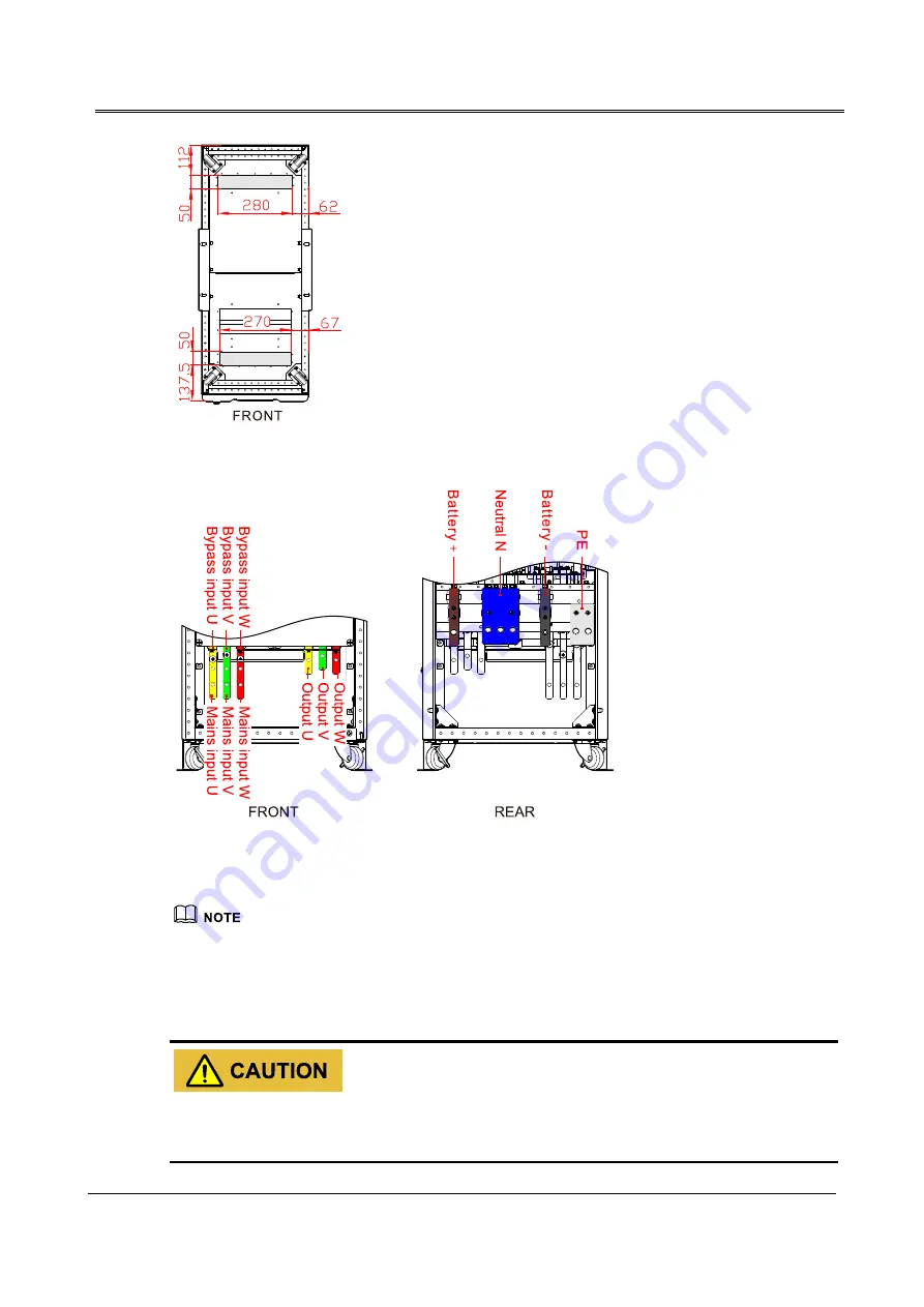
Figure3-29
Down wiring holes diagram of IST7-60, IST7-100, IST7-120
Figure3-30
Wiring terminal diagram of IST7-60, IST7-100, IST7-120
When mains and bypass in one source, the terminal bars of mains and bypass as the mains input,
bypass wiring terminal preferred.
The position of input N and battery N in the same terminal bar at the rear of UPS IST7-60, IST7-100,
IST7-120.
When wiring, ensure that the connection between input/output wire and input/output terminal is reliably,
avoid bad connection or wrongly connection.
Summary of Contents for IST7 Series
Page 1: ...UPS IST7 60 200kVA Series User Manual www aecups com ...
Page 2: ......


