2 Overview
7
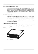
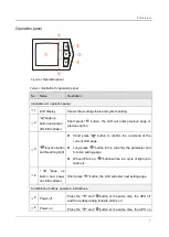
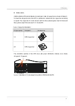
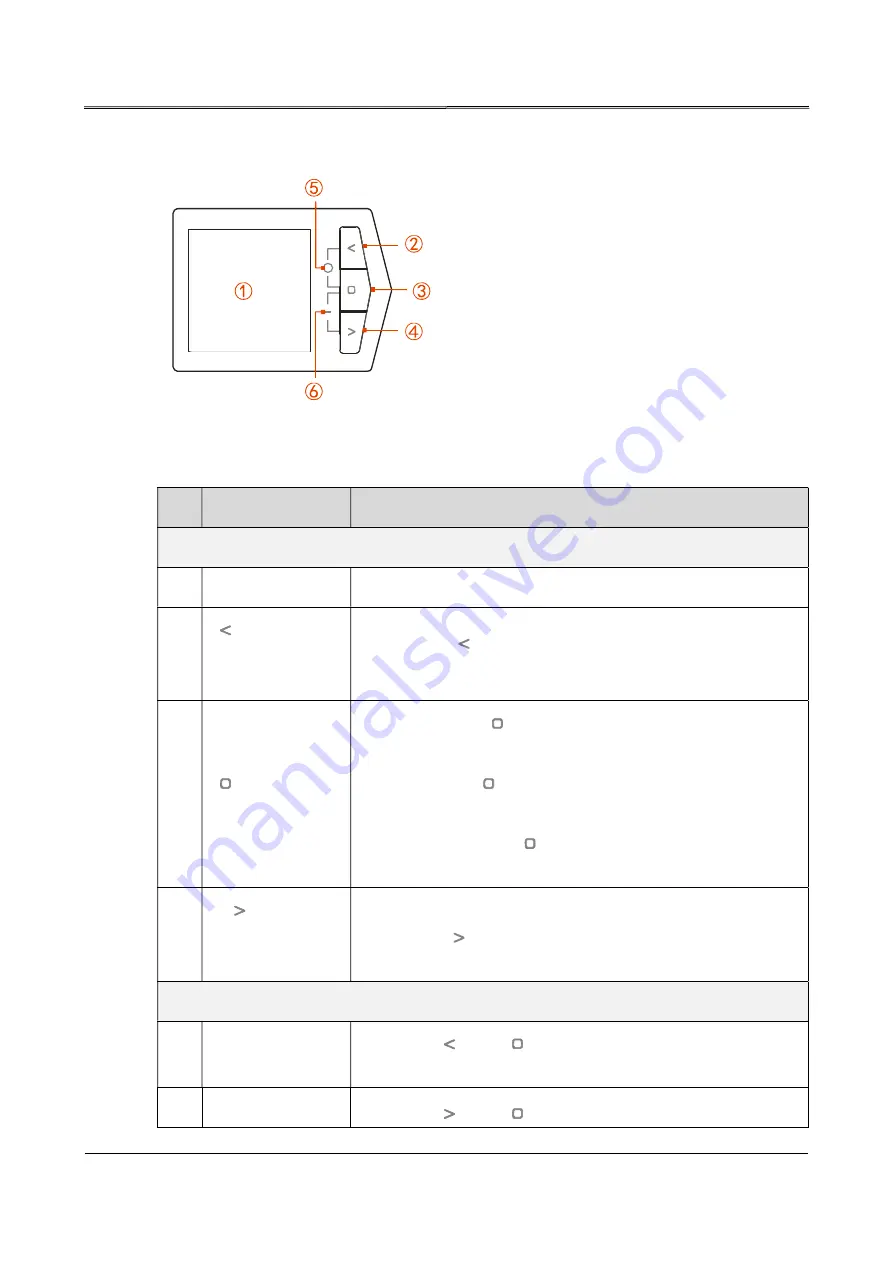
Operation panel
Figure2-2
Operation panel
Table2-1
Illustration for operation panel
No. Name
Illustration
Illustration for operation panel
○
,1 LCD display
Shows the working status and system setting.
○
,2
"
"page up
button and power
off LED indicator
Short press "
" button, the LCD will enter previous page or
previous option.
○
,3
"
"function button
and breathing light
Short press "
" button to confirm the command of the
current LCD page.
Long press " " button for 3s, will entry the parameter and
function setting page.
When UPS is on, "
" button will be in a cycle of light up to
fade out.
○
,4
"
"page
up
button and power
on LED indicator
Short press "
" button, the LCD will enter next setting page.
Combination buttons operation instructions
○
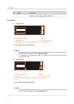
,5 Power off
Press the "
” and " "button at the same time, the UPS off
and the corresponding indicate LED is on.
○
,6 Power on
Press the "
” and "
"button at the same time, the UPS on
Summary of Contents for IST9
Page 1: ...l un I Jet _________ __ AEC IST9 1 0 20 https www uni jet com catalog ibp on line ibp aec ist9...
Page 2: ...UPS IST9 10 20 kVA User Manual...
Page 3: ......
Page 9: ......
Page 52: ...3 Installation 43 Figure3 29 Diagram of 33 mode parallel system wiring of 10kVA 20kVA UPS...
Page 54: ...3 Installation 45 Figure3 31 Diagram of 33 mode parallel system wiring of 30kVA 40kVA UPS...
Page 82: ......

