R-DAS Tiny user’s manual V1.4
©2007 AED Electronics
Step 1 – Power supply:
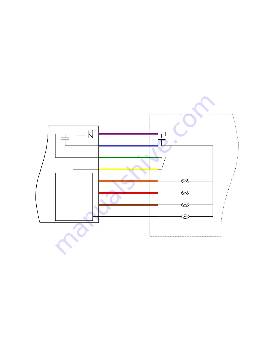
Connect a 9-15V battery to pin 1 (+, purple wire) and pin 2 (-, blue wire). An extra
switch can be installed between pin 1 and the battery to switch the unit on/off.
Step 2 – Safe/Arm and igniter supply:
Pin 3 (green wire) and Pin 4 (yellow wire) have the same function
as connector J13 on the R-DAS Compact (safe/arm connector). A safe/arm switch should be installed to
remotely arm the igniter output stage. Note that the igniter output stage is not powered (and will not fire
igniters) without a connection between pin’s 3 and 4! Like the R-DAS Compact a separate igniter power
supply can be connected to Pin-4.
Step 3 – Connect igniters:
The igniters are connected to Pin’s 5 through 8. To save pins, all igniters have
a common return to the ground (-) of the power supply. If not all igniters are used, replace them with 10k-
Ohm resistors to prevent wrong continuity signals. If a breakwire is needed, simply replace igniter 4 with a
breakwire and configure the R-DAS for breakwire triggering. In case of breakwire triggering only 3 igniter
outputs are available.
1. VCC - Purple
2. GND - Blue
3. Vcap - Green
4. Vign - Yellow
5. Drogue - Orange
6. Main - Red
7. Igniter 3 - Brown
8. Igniter 4 - Black
R-DAS Board
User supplied
Battery for power supply
Firing capacitor
Pyro outputs
Igniter supply
Safe/Arm switch
Drogue igniter
Main igniter
Igniter 3
Igniter 4
Figure 2:
Standard R-DAS Tiny wiring.
4


