background image

16

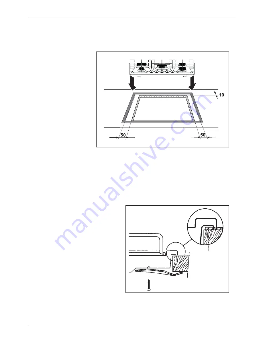
Fitting the Hob into the worktop

Carry out the building in of the hob as follows:

put the seals

supplied with the hob, on
the edges of the cut out:
place them exactly on the
front and rear edge and at
50 mm. from the side
edges, as shown in the
diagram, taking care that
the seals meet without
overlapping;

place the hob in the

cut out, taking care that it is
centred;

fix the hob with the

relevant fixing clamps and
screws, as shown in the diagram.

When the screws have been tightened, the excess seal can be removed.
The edge of the hob forms a double seal which prevents the ingress of liquids.

FO 0199

Seal

FO 2753

Summary of Contents for 35772G

Page 1: ...35772G Gas hob Operating Instructions GB...

Page 2: ...iththehob Thehobgetshotwhenitisinuse Childrenshouldbekeptawayuntilithascooled Childrencanalsoinjurethemselvesbypullingpansorpotsoffthehob During Use This hob is intended for domestic cooking only It i...

Page 3: ...fetyandthe environment Whendisposingofanoldappliance makeitunusable bycuttingoffthecable Thesymbol ontheproductoronitspackagingindicatesthatthisproductmay notbetreatedashouseholdwaste Insteaditshallbe...

Page 4: ...ve 89 336 ElectromagneticalCompatibility Directive 93 68 General Directives andsubsequentmodifications Instructions for the User ImportantSafetyInformation 2 Description of the Hob 5 Operation 6 Maint...

Page 5: ...aretobefoundinthesecondsectionofthismanual Please ensurethat oncethehobisinstalled itiseasilyaccessiblefortheengineerinthe eventofabreakdown WHEN THE HOB IS FIRST INSTALLED Oncethehobhasbeeninstalled...

Page 6: ...easier lighting proceed before putting a pan on the pan support Tolightaburner turntherelevantknobanticlockwiseto maximumposition thenpushitdowntoignitethe burner Uponignition adjusttheflameasrequire...

Page 7: ...eaner For other hobs use Hob Brite or Bar Keepers Friend Pan Supports When washing the pan supports by hand take care when drying them as the enamelling process occasionally leaves rough edges If nece...

Page 8: ...ercapandcrownhavebeen replacedcorrectly e g aftercleaning Check the main jet is not blocked and the burnercrownisclearoffoodparticles Checktheburnercapandcrownhavebeen replacedcorrectly e g afterclean...

Page 9: ...ng 0870 5 929 929 Your call will be routed to your local Service Force Centre FortheaddressofyourlocalServiceForceCentreandfurtherinformationabout ServiceForce pleasevisitthewebsiteat www serviceforce...

Page 10: ...acementofanylightbulbs orremovablepartsofglassorplastic Costsincurredforcallstoputrightanappliancewhichisimproperlyinstalledorcallstoappliancesout sidetheUnitedKingdom Appliancesfoundtobeinusewithinac...

Page 11: ...S 20 mbar VALUE 37 78 MJ m3 Ws 50 7 MJ m3 TYPEOFGAS LPG GAS 28 30 37 mbar VALUE 49 92 MJ Kg Burner Dia Tap By pass 1 100mm Auxiliary 28 Semi rapid 32 Rapid 40 Ultra rapid 56 Aerationadjustmentnone Sup...

Page 12: ...between 5 m3 and 11 m3 If there are other fuel burning appliances in the same room B S 5440 Part 2 Current Edition should be consulted to determine the requisite air vent requirements Location The ho...

Page 13: ...s shown in the diagram Screw the partstogetherwithoutusingexcessiveforce Gas Connection Connection to the gas supply should be with either rigid or semi rigid pipe i e steel or copper Theconnectionsho...

Page 14: ...r a cupboard or drawer If the hob is to be installed above a cupboard or drawer it will be necessary to fit a heat resistantboardbelowthebaseofthehobontheundersideoftheworksurface It is also recommend...

Page 15: ...ingthefurnitureunit inordertoavoid anycontactwiththebottomofthehobwhich can be heated when it is operated The recommendedsolutionisshownindiagram 3 The panel fitted under the hob a should be easily re...

Page 16: ...nd at 50 mm from the side edges as shown in the diagram takingcare that the seals meet without overlapping placethehobinthe cutout takingcarethatitis centred fixthehobwiththe relevantfixingclampsand s...

Page 17: ...ampASTA approved BS 1362 fuse must be used Should the plug need to be replaced for any reason the wires in the mains lead are colouredinaccordancewiththefollowingcode GreenandYellow Earth Blue Neutral...

Page 18: ...nt Ensure that the hob supply cord does not come into contact with surfaces with temperatures higher than 50 deg C Wiring diagram 1 IGNITOR SWITCHES 2 IGNITOR UNIT 2 1 N L N 1 2 3 4 5 6 L N Replacemen...

Page 19: ...ty supply should now be satisfactory Carry out D Resistance to Earth check Inlet wiring faulty Rectify any fault Isolateapplianceand carry out B Insulation check Rectify any fault includingreplacing f...

Page 20: ...hms x 1 scale TestleadsfromLtoNinapplianceterminalblock Ifmeterreads 0 thenthereisa shortcircuit b meter set on Ohm x 100 scale RepeattestwithleadsfromLtoE Ifmeterreadslessthan infinity thereisafault...

Page 21: ...eck by pass simmer adjusted Light burner manually Check continuity from N on the mains connector block and N on theignitorunit Check continuity from L on the mains connector block and the taps ignitio...

Page 22: ...Procedure Re ignitetheburnerandsettoMIN Removethecontrolknob To adjust use a thin bladed screwdriver and turn the adjustmentscrew seediagram untiltheflameissteadyanddoes notextinguish whentheknob is t...

Page 23: ...torsarefitted The gasrateisadjustedtosuit Method Ensurethatthegastapsareinthe OFF position Isolatethehobfromtheelectricalsupply Remove all pan supports burner caps rings crowns and control knobs With...

Page 24: ...r kitchen cleaning and outdoor use More than 55 million Electrolux Group products such as refrigerators cookers washing machines vacuum cleaners chain saws and lawn mowers are sold each year to a valu...

Reviews: