background image

70

Summary of Contents for 341 D

Page 1: ...341 D DE 3161 Dunstabzugshaube Afzuigkap Hotte Cooker Hood Montage und Gebrauchsanweisung Installatie en gebruiksaanwijzing Notice d utilisation et d installation Operating and Installation Instructions ...

Page 2: ...grease filter 59 Charcoal filter 60 Changing the light bulbs 61 Cleaning the hood 61 Special accessories 61 Something Not Working 62 Technical assistance service 63 Service and Spare Parts 63 Customer Care Department 64 Technical Details 64 Mounting accessories included 64 Electrical connection 65 Before beginning installation 66 Fixing a furniture door to the visor 68 Fixing the hood 69 ...

Page 3: ... intended for use by young children or infirm persons without supervision Older children must be supervised if using the appliance Young children should be supervised to ensure that they do not play with the appliance WARNING Ensure that the appliance is switched off before replacing the lamp to avoid the possibility of electric shock This appliance is marked according to the European directive 20...

Page 4: ...tion ducts for rooms in which fuel burning appliances are installed The air outlet installation must comply with the regulations laid down by the relevant local authorities When the unit is used in extraction mode a sufficiently large ventilation hole must be provided with dimensions that are approximately the same as the outlet hole National and regional building regulations impose a number of re...

Page 5: ...p bends in outlet hose to a minimum never install the hoses with an acute angle they must always follow a gentle curve keep the hose as large as possible preferably the same diameter as the outlet hole the length should be no more than 3 metres with one 90 bend 2 metres with two 90 bends Bends of more than 90 will reduce the efficiency of the hood and reduce the airflow Failure to observe these ba...

Page 6: ...d to the coupling ring Fig 1 Note The coupling ring may be placed on the top or on the rear exhaust according to the needs In order to obtain the best performance the hose should have a diameter equal to the outlet hole Fig 2 Fig 1 Top Rear Top Rear hose Coupling ring Rear view Recirculation mode The air is filtered through a charcoal filter and returned to the kitchen Fig 2 You will need an origi...

Page 7: ... the unit s front panel the light switch switches the hood lamp on and off the motor switch switches the motor on and off enabling you to select one of the different speeds The hood is also equipped with a micro switch which can be found under the lower runner of the visor on the right hand side With this micro switch the appliance may be automatically switched on and off by opening and closing th...

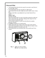
Page 8: ...is very thin approx 1 mm and positioned on the inside of its related support grille The filter should be changed once a month The grille should be cleaned with luke warm water and non abrasive detergent when you change the filter The grease filter can be ordered from your local Service Force Centre Opening the grille Open the latch and remove the grille downwards Fig 3 Removing the filter Remove t...

Page 9: ... grill that protects the extraction motor so that the slots on the filter correspond to the pins on the sides of the motor protection grill Turn the filter clockwise in order to lock the filter into position Remount the grille To remove proceed in the reverse order Always specify the hood model code number and serial number when ordering replacement filters This information is shown on the rating ...

Page 10: ...ld bulb with a new one of the same type Refit the lamp cover grille If the light does not come on make sure the bulb has been inserted in correctly before contacting your local Service Force Centre Cleaning the hood Clean the outside of the hood using a damp cloth and a solution of water and mild washing up liquid Never use corrosive abrasive or flammable cleaning products or products containing b...

Page 11: ... check that the ducting and outlets are not blocked The cooker hood has The safety cut out device has been switched off tripped during operation Turn off the hob and then wait for the device to reset If the hood has been installed below the heights indicated in the installation instructions the motor will cut out frequently which will damage the hood If after all these checks the problem persists ...

Page 12: ... covering your post code area For the address of your local Service Force Centre and further information about Service Force please visit the website at www serviceforce co uk Please ensure that you have read the section What to do if as the engineer will make a charge if the fault is not a mechanical or electrical breakdown even the appliance is under warranty Please note that proof of purchase i...

Page 13: ...orbed power 380 W 220 W Motor 2 x 150 W 140 W Lighting 2 x 40 W E14 2 x 40 W E14 Electrical connection 220 240 V 220 240 V Length of the cable 150 cm 150 cm Fuse rating 5A T 5A T Mounting accessories included 1 allen spanner for TORX screws 1 spacer 2 brackets 2 hooks 1 deflector 2 plastic washers for the spacer 2 wall plugs 1 screw 2 9x9 5 to affix the deflector coupling ring on the outlet hole 4...

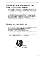
Page 14: ...nector with a distance of at least 3 mm between contacts must be provided Fixed connection of the appliance must only be carried out by an authorised electrician Electrical connection for UK only Safety warnings for the electrician Connect the hood to the mains supply via a double pole switch which has 3 mm minimum separation between the contacts The switch must be accessible at all times The foll...

Page 15: ...de only Choose the exhaust hole to use Fig 6 Only recirculation mode use ONLY the top exhaust hole Check that this once installation is completed is not obstructed and that there is sufficient space so that the purified fumes and steam can return easily into the kitchen Press with decision to take away the prefractured part Top or Rear that closes the exhaust hole and remove it Install the connect...

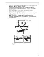
Page 16: ... the rear inside the hood through the opposite slots b Fix the brackets with the screws and threaded bushes Screw the headless screws halfway They will serve to adjust the position of the hood at the moment of installation Fig 7 Note the position of the brackets can be adjusted during installation suitably loosening and retightening the screws that fix them to the hood Ø 5x18 Ø 5x10 Fig 7 Rear vie...

Page 17: ...the arrow on the diagram should face the upper border of the furniture door perform blind holes as indicated K Fig 9 Place the visor over the furniture door and affix with 8 screws Fig 9 L Refit the cover on the cooker hood firstly in the upper track Fig 10 M1 then in the lower track Fig 10 M2 Ø 2 5mm x 6mm max 6mm N3 Ø 4 5 x 13 Fig 8 I I J L Fig 9 K Fig 10 M1 M2 M2 M1 ...

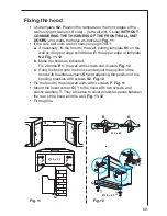
Page 18: ...the wall putting template N1 on the wall so its upper edge coincides with the upper edge of template N2 Fig 11 12 b Make the holes as indicated Fix 2 hooks R to the wall with screws and dowels Fig 12 c Hang the hood onto the hooks and adjust the position of the hood with headless screws S1 and adjusting the position of the hooking brackets with screws S2 Fig 12 Fix the hood to the side wall units ...

Page 19: ...70 ...

Page 20: ...71 ...

Page 21: ...million Electrolux Group products such as refrigerators cookers washing machines vacuum cleaners chain saws and lawn mowers are sold each year to a value of approx USD 14 billion in more than 150 countries around the world AEGElectrolux Addington Way Luton Bedfordshire LU4 9QQ http www aeg co uk AEG Hausgeräte GmbH Postfach 1036 D 90327 Nürnberg http www aeg hausgeraete de Copyright by AEG ...

Reviews: