background image

Installation Instructions

69

Safety Instructions for the Installer

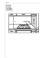
• This hob must be installed by qualified personnel, according to the 

manufacturer’s instructions and to the relevant country standards.

• In respect of fire protection, this appliance corresponds to type Y (IEC 

335-2-6). Only this type of appliance may be installed with a high 
cupboard or wall on one side.

• It is not permitted to fit drawers below the cooking surface.

• Protection against electric shock must be provided by the installation.

• The kitchen unit in which the appliance is fitted must satisfy the 

requirements of DIN 68930 in respect of stability.

• Built-in ovens and cooking surfaces are fitted with special connector 

systems. They may only be combined with appliances with a matching 
system. 

• All cut surfaces are to be sealed with a suitable sealant for protection 

against moisture.

• On tiled work surfaces, the joints in the area where the hob sits on 

the surface must be completely filled with grout.

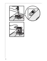
• On natural, artificial stone, or ceramic tops, the snap action springs 

must be bonded in place.

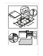
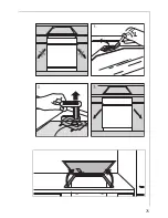
• Ensure that the seal is correctly seated in the frame and that it is sea-

ted against the work surface without leaving any gaps. Additional 
silicon sealant must not be applied, this will make removal more diffi-
cult in the event of the need for service.

• To remove the hob, it must be pressed out from below.

Notes for Switzerland

Contrary to the Household Installation Regulations of the SEV, section 
47330.1, the built-in ovens, hobs and cooking surfaces may be installed 
in flammable materials.
Parts that project into the space underneath the hob must be made on 
non-flammable materials, or be at least 100 mm from the bottom edge 
of the hot plates. Flammable walls and ceilings above the cooking sur-
faces be fitted with fire retardant material in accordance with the reg-
ulations of the fire department in the respective Kanton.
The second rating plate included with the hobs and cooking surfaces 
must be fitted in a location near the appliance so that it is clearly visi-
ble if required, but hidden out of sight (dust and grease free surface).

Summary of Contents for 6130M

Page 1: ...océramique Area di cottura in vetro ceramica Glass Ceramic Cooking Surface Gebrauchsanweisung Montageanweisung Mode d emploi Instructions d installation Istruzioni per l uso Istruzioni per il montaggio Operating Instructions Installation Instructions ...

Page 2: ...ing the appliance 2 3 3 Next to this symbol you receive additional information and practical tips on using the appliance 2 Tips and information about the economical and ecological use of the machine are marked with a cloverleaf In the event of a malfunction these operating instructions contain information on how to rectify faults yourself see the What to do if section In the event of technical pro...

Page 3: ... Switching on the Double Ring Cooking Zone 61 Switching on the Casserole Zone 62 Residual Heat Indicator 62 Usage Tips 63 Pans 63 Cleaning and Care 64 Ceramic Glass 64 The Hob Frame 65 What to do if 66 Installation Instructions 67 Technical Data 67 Regulations Standards Directives 68 Safety Instructions for the Installer 69 Electrical connection 70 Service 71 Installation 72 ...

Page 4: ...ion If your appliance needs repairing please contact your local AEG Service Force Centre If your appliance malfunctions or fractures and cracks or splits appear switch off all cooking zones Disconnect the hob from the electricity supply Child Safety The cooking zones will become hot when the hob is in use Therefore always keep small children away The hob is designed to be operated by adults Do not...

Page 5: ...frame Scratching may occur or the paint damaged Ensure that liquids containing acids e g vinegar lemon or scale remover do not come into contact with the hob frame otherwise matt spots will appear If sugar or a dish containing sugar comes into contact with a hot cooking zone and then melts remove the soiling immediately whilst still hot using a scraper If it cools damage to the surface may occur o...

Page 6: ...d of in the household rubbish You can obtain information about collection dates or public tips from your local Council or Environmental Health Office Warning Before disposing of old appliances make them inoperable Cut off the mains cable Appliance Description Model 6130 M Double Ring Cooking Zone Single Ring Cooking Zone Single Ring Cooking Zone Residual Heat Indicators Residual Heat Indicators Ca...

Page 7: ...box as described in the relevant set of instructions Switching on the Double Ring Cooking Zone Depending on the pot or pan size in the case of double ring cooking zones it is possible to switch with the corresponding touch switch on the ceramic hob to the smaller cooking zone of the larger ring 0 1 Switch on cooking zone in the normal way using the ring switch The small ring is switched on 2 Tap t...

Page 8: ...o switch off the larger ring tap the touch switch again If the casserole zone is completely switched off using the ring switch the larger ring must be switched on again if needed the next time the zone is switched on Residual Heat Indicator An indicator is assigned to each cooking zone This illuminates as soon as the corresponding cooking zone becomes hot and warns against inadvertent touching 1 I...

Page 9: ...ards concave They should under no circum stances be bowed outwards convex 2 Tips on Saving Energy You will save valuable energy if you observe the following tips Always place pans on the cooking zone before switching on Soiled cooking zones and pan bases increase the electricity consumption If possible always fit pans with a lid Switch off the cooking zones before the end of cooking to make use of...

Page 10: ...with a commercially available ceramic glass or stainless steel cleaner e g with Stahl Fix or Vitroclen Light Soilage 1 Wipe the ceramic glass surface with a damp cloth and a little washing up liquid 2 Then rub dry with a clean cloth No residues of cleaner must be left on the surface 3 Once a week thoroughly clean the entire ceramic glass surface with a commercially available ceramic glass cleaner ...

Page 11: ... cooking zone has cooled down already prior to the soilage being removed warm it up again for cle aning Scratches or dark marks on the ceramic glass surface which have been caused by a pan base with sharp edges cannot be removed However they do not impair the function of the cooking surface The Hob Frame 1 Important Do not put vinegar lemons or scale removers on the hob frame otherwise mat spots w...

Page 12: ...nes the required heating circuit is switched on the mains fuse fuse box has blown If this information does not provide you with the necessary assi stance please seek specialist advice 1 Warning Repairs to the appliance may only be carried out by approved service engineers Improper repairs can cause injury or serious mal function If your appliance needs repairing please contact your local AEG Servi...

Page 13: ... this instruction otherwise the warranty will not cover any damage that may occur Technical Data Appliance Dimensions Width 570 mm Depth 500 mm Height 41 mm Cut Out Dimensions Width 560 mm Depth 490 mm Corner radius R3 Power Consumption Single ring cooking zone 145 mm ø 1200 W Double ring cooking zone 120 210 mm ø 2200 W Casserole zone 170 mm ø 265 mm 2400 W Heater Element Voltage 240 V Total Elec...

Page 14: ... 44547 44548 in respect of properties of electric cookers for the household EN 55014 2 VDE 0875 part 14 2 EN 55014 VDE 0875 part 14 12 93 EN 61000 3 2 VDE 0838 part 2 EN 61000 3 3 VDE 0838 part 3 in respect of basic electromagnetic compatibility EMC requirements This appliance complies with the EU Directives 73 23 EWG dated 19 02 1973 Low Voltage Directive 89 336 EWG dated 03 05 1989 EMC Directive...

Page 15: ...ely filled with grout On natural artificial stone or ceramic tops the snap action springs must be bonded in place Ensure that the seal is correctly seated in the frame and that it is sea ted against the work surface without leaving any gaps Additional silicon sealant must not be applied this will make removal more diffi cult in the event of the need for service To remove the hob it must be pressed...

Page 16: ...Installation Instructions 70 Electrical connection Connect the wiring harness plugs with the respective sockets of the same colour of the built in oven or switch box ...

Page 17: ...n noticea ble Under what circumstances does the malfunction occur Prior to the telephone call it is imperative that you make a note of the following appliance code numbers that are given on the rating plate PNC Code 9 digits S No Code 9 digits We recommend you to record the code numbers here so that you always have them at hand PNC S No When will you be charged also during the warranty period when...

Page 18: ...Service 72 Montage Montage Montaggio Installation ...

Page 19: ...73 min 5 mm min 25 mm ...

Page 20: ...74 ...

Page 21: ...75 ...

Reviews: