background image

9

Guarantee Conditions

AEG  offer  the  following  guarantee  to  the  first  purchaser  of  this  appliance.

1. The  guarantee  is  valid  for  12  months  commencing  when  the  appliance  is  handed  over  to

the  first  retail  purchaser,  which  must  be  verified  by  purchase  invoice  or  similar
documentation.
The  guarantee  does  not  cover  commercial  use.

2. The  guarantee  covers  all  parts  or  components  which  fail  due  to  faulty  workmanship  or

faulty  materials. The  guarantee  does  not  cover  appliances  where  defects  or  poor
performance  are  due  to  misuse,  accidental  damage,  neglect,  faulty  installation,
unauthorised  modification  or  attempted  repair,  commercial  use  or  failure  to  observe
requirements  and  recommendations  set  out  in  the  instruction  book.
This  guarantee  does  not  cover  such  parts  as  light  bulbs,  removable  glassware  or  plastic.

3. Should  guarantee  repairs  be  necessary  the  purchaser  must  inform  the  nearest AEG  Service

Force  Centre  (manufacturer’s  service  or  authorised  agent). AEG  reserves  the  right  to
stipulate  the  place  of  the  repair  (i.e.  the  customer’s  home,  place  of  installation  or AEG
workshop).

4. The  guarantee  or  free  replacement  includes  both  labour  and  material.
5. Repairs  carried  out  under  guarantee  do  not  extend  the  guarantee  period  for  the  appliance.

Parts  removed  during  guarantee  repairs  become  property  of AEG.

6. The  purchaser’s  statutory  rights  are  not  affected  by  this  guarantee.

European  Guarantee

If  you  should  move  to  another  country  within  Europe  then  your  guarantee  moves  with  you  to
your  new  home  subject  to  the  following  qualifications:
* The  guarantee  starts  from  the  date  you  first  purchased  your  product.
* The  guarantee  is  for  the  same  period  and  to  the  same  extent  for  labour  and  parts  as  exist

in  the  new  country  of  use  for  this  brand  or  range  of  products.

* This  guarantee  relates  to  you  and  cannot  be  transferred  to  another  user.
* Your  new  home  is  within  the  European  Community  (EC)  or  European  Free Trade Area.
* The  product  is  installed  and  used  in  accordance  with  our  instructions  and  is  only  used

domestically,  i.e.  a  normal  household

* The  electrical  supply  complies  with  the  specification  given  in  the  rating  label.
* The  product  is  installed  taking  into  account  regulations  in  your  new  country.

Before  you  move,  please  contact  your  nearest  Customer  Care  centre,  listed  below,  to  give  them
details  of  your  new  home. They  will  then  ensure  that  the  local  Service  Organisation  is  aware  of
your  move  and  able  to  look  after  you  and  your  appliances.
France

Senlis

+33  (0)3  44  62  29  29

Germany

Nürnberg

+49  (0)911  323  2600

Italy

Pordenone

+39  (0)1678  47053

Sweden

Stockholm

+46  (0)8  738  7910

UK

Slough

+44  (0)1753  219899

Summary of Contents for 95600 G

Page 1: ...e de cuisson Kochmulde Gaskookplaat Piano di cottura Operating and Installation Instructions GB Notice d utilisation et d encastrement BE Gebrauchs und Einbauanweisung BE Gebruiksaanwijzing en Installatievoorschrift NL BE Istruzioni per l uso e l installazione IT ...

Page 2: ... the rating plate located near the gas supply pipe l Do not attempt to modify the hob in any way Child Safety l This hob is designed to be operated by adults Do not allow children to play near or with the hob l The hob gets hot when it is in use Children should be kept away until it has cooled l Children can also injure themselves by pulling pans or pots off the hob During Use l This hob is intend...

Page 3: ...ith oil and fats l Never use plastic or aluminium foil dishes on the hob l Perishable food plastic items and areosols may be affected by heat and should not be stored above or below the hob unit Service l This hob should only be repaired or serviced by an authorised Service Engineer and only genuine approved spare parts should be used Environmental Information l After installation please dispose o...

Page 4: ...s Important Safety Information 2 Instructions for the User 5 Description of the Hob 5 Operation 6 Maintenance and Cleaning 6 Something Not Working 7 Service and Spare Parts 7 Guarantee Conditions 9 Instructions for the Installer 10 Engineers technical data 10 Important safety requirements 10 Location 11 Installation 11 Building over a kitchen unit with door 15 Fitting the hob to the worktop 15 Ele...

Page 5: ... 3 5 6 7 8 2 4 INSTALLATION Any gas installation must be carried out by a registered CORGI installer and in accordance with existing rules and regulations The relevant instructions are to be found in the second section of this manual Please ensure that once the hob is installed it is easily accessible for the engineer in the event of a breakdown WHEN THE HOB IS FIRST INSTALLED Once the hob has bee...

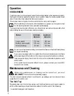
Page 6: ...ot ignite turn the control knob to zero and try again When switching on the mains after installation or a power cut it is quite normal for the spark generator to be activated automatically To ensure maximum burner efficiency you should only use pots and pans with a flat bottom fitting the size of the burner used see table Burner minimum maximum diameter diameter Large rapid 160 mm 260 mm Medium se...

Page 7: ...moistened soap impregnated steel wool pad can be used with caution if the marks are particularly difficult to remove After cleaning be sure to wipe dry with a soft cloth Something Not Working If the hob is not working correctly please carry out the following checks before contacting your local AEG Service Force Centre SYMPTOM n There is no spark when lighting the gas n The gas ring burns unevenly ...

Page 8: ...Force Centre CUSTOMER CARE For general enquiries concerning your AEG appliance and for further information on AEG products contact our Customer Care Department by letter or telephone as follows Customer Care Department AEG Domestic Appliances 55 77 High Street Slough Berkshire SL1 1DZ Tel 08705 350 350 If after all these checks your hob still does not operate correctly contact your local AEG Servi...

Page 9: ...nd the guarantee period for the appliance Parts removed during guarantee repairs become property of AEG 6 The purchaser s statutory rights are not affected by this guarantee European Guarantee If you should move to another country within Europe then your guarantee moves with you to your new home subject to the following qualifications The guarantee starts from the date you first purchased your pro...

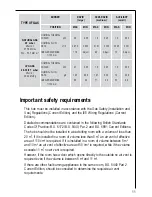
Page 10: ...PARK Spark Generator Ispra Control s BF 50046 230 240V 0 6 YA T120 Spark Gap Fixed HEAT INPUT Instructions for the Installer Engineers technical data Rear Left Burner 1 9 kW 6483 BTU HR semi rapid Front Left Burner 2 9 kW Natural Gas 9895 BTU HR rapid 2 7kWL P G 9212BTU HR Rear Right Burner 1 9 kW 6483 BTU HR semi rapid Front Right Burner 1 0 kW 3412 BTU HR auxiliary APPLIANCE CLASS 3 APPLIANCE CA...

Page 11: ...ile if the volume exceeds 11 m3 no air vent is required However if the room has a door which opens directly to the outside no air vent is required even if the volume is between 5 m3 and 11 m3 If there are other fuel burning appliances in the same room B S 5440 Part 2 Current Edition should be consulted to determine the requisite air vent requirements BURNER RAPID SEMI RAPID AUXILIARY large medium ...

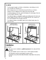
Page 12: ...m must be allowed from the edges of the hob The minimum distance combustible material can be fitted directly above the hob is 700 mm 650 mm 400 mm 400 mm 100 mm 50 mm 50 mm 55 mm 600 mm 700 mm 400 mm 100 mm 400 mm 50 mm 55 mm 50 mm CLEARANCES REQUIRED WHEN FITTING THE GAS HOB WITHOUT A COOKER HOOD ABOVE CLEARANCES REQUIRED WHEN FITTING THE GAS HOB WITH A COOKER HOOD ABOVE FO 0813 FO 0812 Installat...

Page 13: ...shoulder on the end of the thread fitted to the hob connecting pipe Failure to ensure the correct assembly will cause leakage of gas Gas Connection Connection to the gas supply should be with either rigid or semi rigid pipe i e steel or copper The connection should be suitable for connecting to RC 1 2 1 2 BSP male thread When the final connection has been made it is essential that a thorough leak ...

Page 14: ...given in the diagram Building In Building over a cupboard or drawer If the hob is to be installed above a cupboard or drawer it will be necessary to fit a heat resistant board below the base of the hob on the underside of the work surface It is also recommended to carry out the electrical connection to the hob as shown in diagrams 1 and 2 see next page ...

Page 15: ...tchen unit with door Before fitting the hob into the cut out an adhesive seal must be fitted to the underside outside edge of the hob It is essential that no gaps are left in this seal in order to prevent spillage near the hob seeping into the cabinet below 1 Remove the pan supports the burner caps and crowns and turn the hob upside down taking care the ignition candles are not damaged in this ope...

Page 16: ...pproved BS 1362 fuse must be used Should the plug need to be replaced for any reason the wires in the mains lead are coloured in accordance with the following code Green and Yellow Earth Blue Neutral Brown Live 1 Connect the green and yellow earth wire to the terminal in the plug which is marked with the letter E or the earth symbol or coloured green and yellow 2 Connect the blue neutral wire to t...

Page 17: ...mm between the switch contacts and of a type suitable for the required load in compliance with the current electric regulations The switch must not break the yellow and green earth cable at any point Ensure that the hob supply cord does not come into contact with surfaces with temperatures higher than 50 deg C Wiring diagram 1 TAPS IGNITORSWITCHES 2 IGNITOR UNIT 1 2 L N 0 220 240 1 2 3 4 ...

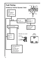
Page 18: ...ty supply should now be satisfactory Carry out D Resistance to Earth check Inlet wiring faulty Rectify any fault Isolate appliance and carry out B Insulation check Rectify any fault including replacing fuses as necessary NO YES SOCKET face view PLUG with cover removed Earth Wire Green Yellow Neutral Wire Blue FUSE E N L Brown Blue Green Yellow Green Yellow Brown Blue NO YES ...

Page 19: ...Test leads from L to N in appliance terminal block If meter reads 0 then there is a short circuit b meter set on W Ohm x 100 scale Repeat test with leads from L to E If meter reads less than infinity there is a fault NOTE Should it be found that the fuse has failed but no fault is indicated a detailed continuity check i e by disconnecting and checking each component is required to trace the faulty...

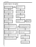
Page 20: ...ass simmer adjusted Light burner manually Check continuity from N on the mains connector block and O on the ignitor unit Check continuity from L on the mains connector block and the taps ignition switches Check continuity from ignition switches connector to ignitor unit Check continuity from the tip of each electrode to the terminals 1 to 4 on the ignitor unit Check for breaks in the insulation of...

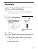
Page 21: ...rol knob 3 The adjustment screw is located down the centre of the gas tap control shaft To adjust use a thin bladed screwdriver and turn the adjustment screw until the flame is steady and does not extinguish when the knob is turned from MIN to MAX Repeat this procedure for all burners Pressure Testing 1 Remove left hand pan support and front left burner cap and crown 2 Fit manometer tube over the ...

Page 22: ... 3 Remove all pan supports burner caps rings crowns and control knobs 4 With the aid of a 7mm box spanner the burner injectors can then be unscrewed and replaced by the appropriate LPG injectors TO ADJUST THE GAS RATE With the aid of a thin bladed screwdriver completely tighten down the by pass adjustment screw which is located down the centre of the gas tap control shaft Upon completion stick the...

Reviews: