33
PROTECT B. 3000
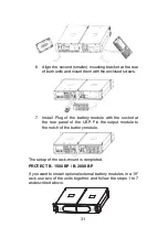
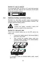
Connect the supplied battery module cable from extended
battery module to the external battery port of the rear of UPS.
If continuing to add up extended battery module, repeat above
steps.
5.3
Emergency Power Off (EPO) set up
PROTECT B. 1500, 2000 and 3000 include EPO port that
allows power to be shut down the protected equipment
immediately and does not follow the shutdown procedure from
any power management software.
i
Note:
After pressing the EPO all outputs of the UPS are
without power. For restarting the system you have
to quit / reset the EPO and manually restart the
UPS by pressing the on / off button.
Follow the procedure to install the EPO switch as below.
1.
Check the UPS is turned off.
2.
Remove the power supply from the EPO cradle
on the rear of the UPS by loosening the two
outer screws.
3.
Connect isolated, normally-open, dry contacts
(rated to handle 60Vdc maximum, 30Vac RMS
maximum, and 20mA maximum) across the
EPO device to Pin 1 and Pin 2.
4.
Use non-shield wiring, size 0,3 mm² - 0.75
mm². Plug the connector into the socket and fix
it by screwing the two outer screws tight.
5.
Verify that the externally-connected EPO switch
is not activated to enable power to the UPS
output receptacles.
6.
Plug in the UPS, then pressing power switch
button to turn on the UPS.
Summary of Contents for A PROTECT B. 1500
Page 14: ...14 3 3 Certification ...

