--------------------------------------------------------------------------------15/20--------------------------------------------------------------------------------
2.
Using the RS232 interface of the reader ARE i2
GT<CR> -> reading the transponder in the field of antenna 2
3.
Using the RS232 interface of the AMP 4/8
MP4<CR> ->switching to antenna channel 4
4.
Using the RS232 interface of the reader ARE i2
GT<CR> -> reading the transponder in the field of antenna 4
5.2
Controlling via reader ARE i2 (mode 2)
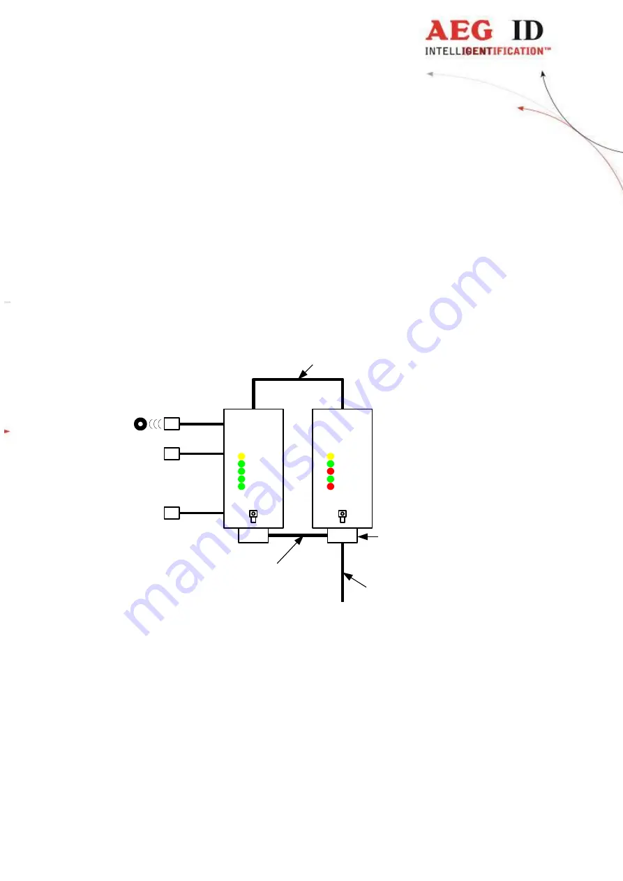
Figure 4: system overview controlling via reader ARE i2 (mode 2)
In mode 2 the power supply and the data line of the AMP 4/8 is connected directly to the SAB cap of the
ARE i2.
There is a PC connection cable available with this wiring.
It is important not to change the SAB cap of the AMP 4/8 with the SAB cap of the ARE i2.
If you use your own cable be sure with the pin assignment of the AMP 4/8 (chapter 2.4.4.3) and the
ARE i2.
The typical sequence in mode 2 is as follows:
antenna 1
antenna 2
antenna connection
RS232
+
power supply (z.B PC connection
cable for ARE i2 und AMP 4/8)
.
.
.
antenna 8
power supply
+
data line
between AMP and ARE i2
Vcc
1
2
4
8
AEG
ID
AMP 4/8
L1
L2
L3
L4
L5
AEG
ID
ARE i2
SAB cap


