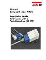
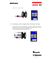
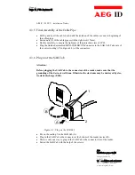
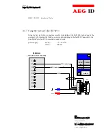
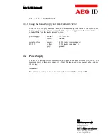
background image

Manual
Compact Reader ARE I2

Installation Guide
for Systems with a
Serial Interface (RS 232)

Summary of Contents for ARE I2

Page 1: ...Manual Compact Reader ARE I2 Installation Guide for Systems with a Serial Interface RS 232 ...

Page 2: ...d Diameter of the Used Cables 8 4 3 2 Assembling of the Cable Pipe 8 4 3 3 Mounting of the Power Supply Cable 9 Assembling of the Power Supply and Data Cable Single Cable Pipe 10 4 3 5 Final Assembly of the Cable Pipe 11 4 3 6 Plug in of the SAB Cab 11 4 3 7 Using the Service Cable ID 70213 12 4 3 8 Using the Power Supply and Data Cable ID 70212 13 4 4 Power Supply 13 5 VISUAL SIGNAL LAMPS 14 6 SE...

Page 3: ...meters 22 7 1 2 Basic Data Exchange Process 23 7 1 3 ReadOnly Transponder 23 7 1 4 R W Transponder 23 7 1 4 1 Standard Read Process Serial Number of the Transponder GT 23 7 1 4 2 Selective Read RD 24 7 1 4 3 Writing Process WD 24 7 2 Operating Mode 0 Continuous Reading 26 7 2 1 Settings of the Reader Most Used Parameters 26 8 INSTRUCTIONS 28 8 1 General Instructions 28 8 2 Special Instructions for...

Page 4: ...Manual Page 4 33 Revision 01 ARE I2 RS 232 Installation Guide AEG Identifikationssysteme GmbH Söflinger Straße 100 D 89077 Ulm Tel 49 0 731 933 1340 1877 Fax 49 0 731 933 1855 e mail info AEGID de ...

Page 5: ...l RS 232 Interface is placed inside of the housing allowed baud rate are up to 19200 Bit s the allowed supply voltage is 9 to 30VDC low power consumption of reader 1 2 Watt high reliability for reading and writing within an industrial environment compact housing of the reader with multiple ways for mounting the cabling concept of the reader is optimised to service demands the protection class of t...

Page 6: ...port while using the integrated serial RS 232 Interface of the reader The side of the housing showing the antenna symbol must not be brought next to a metal sur face This could lead to a significant change of the properties of the antenna circuit which in turn reduces the reading range considerably Environmental electromagnetic noise may also reduce the specified reading performance Special hints ...

Page 7: ... next to a metal surface This could lead to a significant change of the properties of the antenna circuit which in turn reduces the reading range considerably With the help of the plastic bars the reader can mounted or screwed on to the most fastening elements without open the housing of the device 4 2 Grounding of the Reader To get reliable reading results the reader must be grounded The connecto...

Page 8: ... two PG9 cable pipes ID 70219 SAB Cab without any cable pipe The cabling is done by the customer himself 4 3 1 Allowed Diameter of the Used Cables The allowed diameters of the cables used for data link and power supply must be in the range from 3 5 to 8mm For this case IP 65 is reached 4 3 2 Assembling of the Cable Pipe If no preassembled SAB Cab are used Best Nr ID 70214 the assembling must be do...

Page 9: ...able fastener 3 and the cable pipe of the SAB Cab as well 1 to 4 to the cable Figure 4 2 Arranged Parts for Mounting Remove the outer isolation of the cable at a length of 6cm Remove the isolation of the wires at a length of 6 mm and stick a covering hull to the litz wire Put the cable to the cable pipe The length of the cable coming out the SAB Cab must long enough to do all further installation ...

Page 10: ...the cable is also done inside of the SAB Cab Instead of an 2 wire power supply cable there is now an 5 wire data cable needed The diameter of the inner wires must be big enough to keep the voltage drop in the specified range The steps to mount the cable is decried in Chapter 4 3 3 B A D C E green L US US UL black shielding NC shielding 9 30V DC GND 0V TXD RXD NC ARE I2 V DC TxD reader GND RxD read...

Page 11: ...ction class of IP 65 Plug the finished assembled MINI COMBICON Connector to the SAB Cab Take care of the correct coding 7 in Figure 4 2 of the connectors 4 3 6 Plug in of the SAB Cab Attention Before plugging the SAB Cab to the connectors of the reader make sure that the grounding of the device is well done Otherwise the electronic may be destroyed by elec trostatic discharge ESD Figure 4 3 Plug o...

Page 12: ... 70213 Using the Service Cable no special assembly work inside of the SAB Cab has be done by the customer After making the link to a power supply and plug in the Sub D 9 Connector to the Com Data Port of an PC the reader is ready to work power supply brown 9 30 Volt white Ground RS232 9 Pins Sub D female 1 2 3 4 5 6 7 8 9 RxD reader TxD reader GND U S1 US1 green ARE I2 shielding V 24V GND 0V TXD R...

Page 13: ...customer After making the link to a power supply and to the connector block of Serial Data Port the reader is ready to work power supply brown 9 30 Volt white Ground serial Interface green RxD reader receives data s RS 232 yellow TxD reader sends data s grey ground 4 4 Power Supply The device is designed for DC Current with an voltage in the range between 9 to 30VDC The minimum power of the power ...

Page 14: ...che Objekterkennung und Verfolgung L 1 L2 L4 L3 L5 ARE I2 5 Visual Signal Lamps To show the operational state or results there are 5 LED at the side of the housing L1 twinkles if the processor works L2 lit if the latest reading process was successful L3 lit if the latest reading process was a NoRead L4 lit if the reader receives data s at the serial data port Rx L5 lit if the reader sends data s a...

Page 15: ...ntrol character serves as com mand line terminator Command codes and parameters that means all letters and numerical values are princi pally transmitted as a sequence of ASCII characters the value 255 decimal consequently as 32H 35H 35H the command RST as 52H 53H 54H The protocol format is as follows command SP parameter CR The space character SP separates commands from parameters and the CR chara...

Page 16: ...ng an parameter value Example Command MD CR Output 1 CR If a single CR is input the reader answers with a single CR Example Command CR Output CR Please note If echo mode is active a single CR forces the reader to output CR CR echo plus output 6 2 Error Codes If a command is not entered correctly the reader sends one of the following error codes Wrong command NAK 00 CR Wrong parameter NAK 02 CR 6 3...

Page 17: ...Reads Through the setting CN 1 all NoRead results are suppressed on the serial interface Input format CN SP parameter CR Parameter Value Function 0 issue NoReads on serial interface default value 1 suppress NoReads on interface Output example 0 CR Please note The CN parameter is only active if the GT Command is applied or the reader is in the Continuos Reading Mode In the MD 2 any way a CR is sent...

Page 18: ...eading cycles Output sequence after filtering with CN 0 and CID 1 Output sequence after filtering with CN 1 and CID 1 N N N A A A A N N N N N A N N A N N N A A A N A A B A C C C N N N A N B A C A B A C N N B B B B B N N N B B B B N N N N B N N N N N B N N N B B B B B N B B B B N N N N N N B N N N N B Table 6 example for the effect of the CID function Annotation The internal reference number is del...

Page 19: ...ho function setting Input format EC SP parameter CR Parameter v Function 0 echo on 1 echo off Output example 0 CR Note The default value of the parameter EC depends on the particular reader 6 7 BD Baudrate The command BD enables the change of the baud rate The settings are effective after a warm start using the RST command Input format BD SP parameter CR Parameter Parame ter Function 0 4800 baud 1...

Page 20: ...se has always the default value 100ms Input format TOR SP parameter CR Parameter Function 0 limits the reading process duration to exactly one reading cycle 1 limits the reading process duration to maximum 1 times TB 2 limits the reading process duration to maximum 2 times TB 255 limits the reading process duration to maximum 256 times TB Output example 2 CR 6 9 VS Show Parameter The command VS li...

Page 21: ...In operating mode 2 the exciter is always turned off Triggered by the software command GT RD WD the exciter is activated After successful reading or writing of a transponder number the exciter is turned off automatically Figure 7 1 1 Software triggered reading operation If the first reading cycle yields no result NoRead the on time of the exciter is limited by the parameter TOR time out reader Rea...

Page 22: ...ameters The default operation mode is changed by sending a software command to the reader In combination with an R W transponder the serial number of the transponder device is read out only MD 2 triggerd by an software command most used parameters CID 0 no suppression of repeatedly read Ids CN 0 no suppression of NoReads NID 1 failure protection selection guide 2 out 2 transponder codes TOR XYZ ma...

Page 23: ...nge of the whole memory can only be done if the reader is set to the Mode 2 selective Read RD and write WD 7 1 3 ReadOnly Transponder Start the reader with the command GT plus CR Wait for the answer max time to wait is given by the value of TOR Parameter Analyse the received answer 10 characters plus CR The reading result may also been judged according the LED s LED L2 lit if there was a successfu...

Page 24: ...us CR Allowed characters 0 to F The NoRead Code is set to XXXXXXXX The result of the reading process may also be seen at the LED s LED L2 lit if there was a successful read LED L3 lit if there was a No Read Example RD SP 20 CR read block 20 RD SP 16 SP 33 CR read all blocks from 16 to 33 Allowed Values block numbers of the transponder IC ALGO 9 1kBit Memory 3 33 Serial Number block 32 ALGO 6 2kBit...

Page 25: ...ters plus CR ACK CR Writing process was successful NAK CR Writing process was not successful NOT CR The response of the transponder was not readable The result of the writing process may also seen at the LED s LED L2 lit if there was a successful write LED L3 lit if there was no successful write Example WD SP 20 SP 0 1 2 7 A C D F CR Write to block 20 Allowed Values block numbers of the transponde...

Page 26: ... the reading information is evaluated After that data ei ther transponder number or NoRead code is output to the serial interface Figure 7 2 continuous operation 7 2 1 Settings of the Reader Most Used Parameters The default operation mode is changed by sending a software command to the reader In combination with an R W transponder the serial number of the transponder device is read out only MD 0 c...

Page 27: ...nger Straße 100 D 89077 Ulm Tel 49 0 731 933 1340 1877 Fax 49 0 731 933 1855 e mail info AEGID de NID 1 failure protection selection guide 2 out 2 transponder codes The result of the reading process may also seen at the LED s LED L2 lit if there was a successful read LED L3 lit if there was an NoRead ...

Page 28: ...ly on the orientation between Reader and Transponder To get the maximum reading distance the ori entation between reader and transponder must be well suited The best orientation depends on the type of antenna inside of the housing ferrite type or plane coil type and the applied transponder disc or glass transponder To get a reliable readings or writings the time of transponder while crossing the s...

Page 29: ...n of the magnetic field comming from the transponder and the write pattern do ne by the base station shows a lot of similarities Therefore read write systems may interfere each other The minimum distance between two antennas mounted next to each other and the size of the interference must be determined for each application itself Below there are listed several parameters that will influence the si...

Page 30: ...line If there are questions or suggestions please be so free an phone Fax 49 0 731 933 1855 e mail info aegid de http www aegid de 10 Reference Documentation 1 Manual ASB 1 0 AEG ID standard operating system 11 Revisions The initial English Edition is based on Revision 1 of the German Manual Edition Nr date 19 12 2001 09 09 03 Revision 00 01 02 03 Changes Rev 00 Initial Edition Rev 01 Chapter 8 2 ...

Page 31: ...raße 100 D 89077 Ulm Tel 49 0 731 933 1340 1877 Fax 49 0 731 933 1855 e mail info AEGID de 12 Appendix 12 1 Best Orientation for an F Type Reader Compact Reader ARE I2 Internal Antenna F Typ 1 1 0 2 0 3 0 8 0 1 0 2 0 3 0 5 1 0 1 5 2 0 25 30 F Typ Reading Coil Best Orientation Disc Transponder Rod Transponder ...

Page 32: ...traße 100 D 89077 Ulm Tel 49 0 731 933 1340 1877 Fax 49 0 731 933 1855 e mail info AEGID de 12 2 Best Orientation for an L Type Reader Compact Reader ARE I2 Internal Antenna L Typ Bauteilname 1 1 0 2 0 3 0 8 0 1 0 2 0 3 0 5 1 0 1 5 2 0 25 30 L Typ Reader Coil Best Orientation DiscTransponder Rod Transponder ...

Page 33: ...3 33 Revision 01 ARE I2 RS 232 Installation Guide AEG Identifikationssysteme GmbH Söflinger Straße 100 D 89077 Ulm Tel 49 0 731 933 1340 1877 Fax 49 0 731 933 1855 e mail info AEGID de 12 3 Assembling of the SAB Cab ...

Reviews: