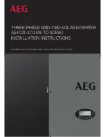
background image

THREE-PHASE GRID-TIED SOLAR INVERTER 

AS-IC01-2 (12 kW TO 30 kW)

INSTALLATION INSTRUCTIONS

PD201808 AEG GRID-TIED THREE-PHASE SOLAR INVERTER (12-30 kW)  V.2-18 EN

Summary of Contents for AS-IC01-12000-2

Page 1: ...THREE PHASE GRID TIED SOLAR INVERTER AS IC01 2 12 kW TO 30 kW INSTALLATION INSTRUCTIONS PD201808 AEG GRID TIED THREE PHASE SOLAR INVERTER 12 30 kW V 2 18 EN ...

Page 2: ...infor mation to ensure that your PV installation runs smoothly and achieves optimal yields over its whole lifecycle AEG grid tied solar inverters are tested and approved by acknowledged independent certification authorities and can only be installed by qualified professional companies Please observe the standards and regulations applying to photo voltaic systems in the relevant countries as well a...

Page 3: ...d grid connection structure 9 2 2 Product Appearance 10 2 3 Labels 11 2 3 1 Packaging labels 11 2 3 2 Product label 12 2 3 3 Product models 13 2 4 Technical parameters 13 2 5 Dimensions and weight 15 3 Installation 15 3 1 Unpacking inspection 15 3 2 Before installation 18 3 2 1 Installation tools 18 3 2 2 Installation place 18 3 2 3 Connection cables 20 3 2 4 Miniature circuit breakers 20 3 3 Mech...

Page 4: ...4 1 Monitoring parameters 34 5 4 2 History 35 5 4 3 Statistics 35 5 4 4 Parameter settings 35 5 4 5 System Information 42 5 4 6 Faults 42 5 4 7 Inverter control 42 5 4 8 Mode settings 44 5 5 Grid selection 44 6 Monitoring communication 46 6 1 Standard communication 46 6 2 Optional communication 47 6 3 AEG WiFi200 AEG WiFi Stick communication module 47 6 3 1 AEG WiFi Stick product overview 47 6 3 2...

Page 5: ...ace Product surface may become hot Do not touch Note Useful information for product maintenance and operation is provided Table 1 Icon meaning 1 2 Safety Guidelines 5 minutes Look for any visible damage to the package or the product itself Double check the order information and the product nameplate to ensure the products are of the ordered type Should you find any prob lems contact the shipping c...

Page 6: ...e burns Do not touch The inverter must be reliably grounded before operation Do not unauthorizedly open the inverter cover The electrical parts and components inside the in verter are electrostatic Take measurements to avoid electrostatic discharge during relevant opera tions Technical personnel Operators who can carry out installation wiring commissioning maintenance troubleshooting and replaceme...

Page 7: ...ut voltage otherwise inverter damage may occur The positive and negative pole of solar modules should not be grounded otherwise irrecoverable damage may occur Ensure the proper grounding of the inverter improper connection or no ground ing may cause the inverter to stop Ensure reliable installation and electrical connection 1 2 2 Grid tied operation Only qualified electricians are allowed to opera...

Page 8: ...y and has to be stored please follow the below recommendations Do not remove the packaging Store the inverter in a dry clean place to prevent erosion caused by dust and water vapor Make sure that storage temperature stays in the range 40 C 70 and relative humidity stays in the range 5 RH 95 RH If you have to stack the inverters follow the original stacking configuration from the original shipment ...

Page 9: ...e of photovoltaic power generation system Solar energy is converted into DC electric energy through solar modules and is then transformed by grid tied solar inverters into sinusoidal AC energy which has the same frequency and phase as the public grid this electricity can then be fed to the grid AEG AS IC01 2 series of three phase grid tied solar inverters are only deployed in solar grid tied power...

Page 10: ...NVERTER 12 30 kW V 2 18 EN 9 2 1 2 Supported grid connection structure The AEG inverter series AS IC01 2 supports TN S TN C TT and IT grid connection When applied to the TT connection the N to PE voltage should be less than 30V Figure 2 Grid type ...

Page 11: ...nput 4 DC input port For connecting solar modules 5 Communication port RS485 and EXT communication port 6 AC terminal For connecting the AC output 7 Installation hanger For connecting inverter and installation bracket 8 Fan mounting plate Air inlet For fan fixing 9 Handle For transportation and lifting 10 Safety warnings Indicating precautions to be taken 11 Labels Indicating the rated parameters ...

Page 12: ...r supplier as soon as possible before attempting product installation 2 3 1 Packaging labels Packaging labels include relevant information such as the inverter type related certification standards protective degree gross weight and product serial number Figure 4 Example of packaging label Trademark Product type Model Product Namecode Serial Number Product characteristics Certification standards Ma...

Page 13: ...ample of product label TÜV product certification mark The product is TÜV certified CE mark The product complies with the CE directive EU WEEE mark The product cannot be disposed of as household waste Safety warning Hazardous electricity can cause shock burs or death For proper use the installation manual should be consulted Product type Model Product Namecode DC Input parameters AC Output paramete...

Page 14: ...s notice Please refer to the related product datasheet which you can also find under www aeg industrialsolar de Service Product Datasheet for the latest parameters Model Three phase inverters AS IC01 xxx 2 up to 30 kW 12kW 15kW 17kW 20kW 25kW 30kW DC input Max DC voltage V 1000 1000 1000 1000 1000 1000 Starting voltage V 200 200 200 300 300 300 MPPT voltage V 180 800 180 800 180 800 280 800 280 80...

Page 15: ... 5 inches LCD support backlight display System language English German Dutch Communication RS485 standard Ethernet WiFi oprional DC terminal BC03A BC03B Noise dB A 55 Installation mode Wall installation Others Grid standards DIN VDE 0126 1 1 2013 VDE AR N 4105 2011 DIN VDE V 0124 100 2012 IEC 61727 IEC62116 AS NZS 4777 2 2015 NB T32004 2013 IEC 60068 2 1 2007 IEC 60068 2 2 2007 IEC 60068 2 14 2009...

Page 16: ...AS IC01 30000 2 660 520 250 53 Table 5 Dimensions and weight of the products in the AS IC01 2 series up to 30 kW 3 Installation The following section describes how to install and connect the inverter to the grid tied solar system Please ensure that all installation requirements are met before installation Only qualified electricians are allowed to install the inverter 3 1 Unpacking inspection When...

Page 17: ...verters of AS IC01 2 series 12 kW to 17 kW No Item Quantity 1 Product AS IC01 12000 2 AS IC01 15000 2 AS IC01 17000 2 1 unit 2 Installation bracket 1 unit 3 Wall plate cutout template 1 unit 4 Operation manual Quick Installation Guide 1 unit 5 Communication connector 1 unit 6 DC connector 4 pairs 7 Expansion bolts M8 60 6 units 8 Hexagon combination bolt M8 20 6 units 9 Hexagon combination bolt M6...

Page 18: ...roduct AS IC01 20000 2 AS IC01 25000 2 AS IC01 30000 2 1 unit 2 Installation bracket 1 unit 3 Wall plate cutout template 1 unit 4 Operation manual Quick Installation Guide 1 unit 5 Communication connector 1 unit 6 DC connector 6 pairs 8 pairs 7 Expansion bolts M8 60 6 units 8 Hexagon combination bolt M8 20 6 units 9 Hexagon combination bolt M6 16 2 units 10 AC ring terminal 5 units Table 6B Packin...

Page 19: ...ading the inverter parameters smoothly see figure 8A 2 Select a well ventilated place sheltered from direct sun radiation and rain 3 Allow sufficient space around the inverter to enable easy installation and removal from the mounting surface as well as air circulation see figure 8B 4 When installing more than one inverter please ensure that enough space is kept between the individ ual inverters Th...

Page 20: ...OLAR INVERTER 12 30 kW V 2 18 EN 19 Figure 8C Side by side installation spacing requirement mm Figure 8D Correct and not correct installation position of the AEG inverter Figure 8A Optimal mounting height mm Figure 8B Installation spacing mm ...

Page 21: ...on of the inverter and circuits it is recommender to place micro breakers or fuses on the DC input end and on the AC output end of the inverter The wiring shall follow local electric codes Choose proper cables for power input and output lines Input and output cables shall be solar cables suitable for outdoor use The below table reports the recommended specifications for the micro breakers Model DC...

Page 22: ...ter on concrete wall The inverter installation should be vertical to the horizontal surface 3 3 1 Installation of three phase inverters Figure 10 Installation bracket Model Installation hole A mm B mm AS IC01 12000 2 AS IC01 15000 2 AS IC01 17000 2 AS IC01 20000 2 AS IC01 25000 2 AS IC01 30000 2 400 400 Table 11 Installation brackets specifications Please follow the below installation steps for th...

Page 23: ... ensure the installation is firm enough tightening torque 13 N m 5 Hang the inverter to the installation bracket and ensure the installation is firm enough Figure 11D Fixing the installation brackets Figure 11E Inverter installation 6 Ensure that the inverter is installed properly and tighten the M6 x 16 bolts into the screw holes on the left and right side of the inverter tightening torque 4 N m ...

Page 24: ...ified personnel can perform the wiring work All electrical installations must be in accordance with local and national electrical codes All cables must be firmly attached undamaged properly insulated and adequately dimensioned Read and follow the instructions provided in this section while observing all safety warnings Always note the rated voltage and current defined in this manual Never exceed t...

Page 25: ... torque of 2 5 3 Nm Ensure the poles of solar modules are well connected with the connectors 3 After the DC connector is connected use a multimeter to measure the voltage of the DC input string verify the polarity of the DC input cable and ensure that the voltage of each string is within the allowa ble range of the inverter as shown in picture 13B below Figure 13B DC input voltage measuring Only D...

Page 26: ...wiring is done correctly and that it is tight enough Connection steps of three phase inverters 1 Before AC connection take lightning and short circuit protection measures in accordance with the local electri cal safety codes only cables qualified according to the local electrical safety laws and regulations should be used for connection Only with the inverter of the local electric power company ca...

Page 27: ...n the waterproof connector to complete the waterproofing of the cable as shown in Figure 14F below Figure 14E Connection of wire and connector Figure 14F Fixing the waterproof cover of the junction box 4 Operation The following section describes the detailed operation of the inverter covering pre inspection operation grid tied oper ation stopping and inverter maintenance 4 1 Inspection before oper...

Page 28: ...cation choice Keep the inverter turned on at least 30 minutes to allow for charging of the internal clock battery Please start the inverter as follows 1 Ensure the requirements mentioned in section 4 1 are met 2 Switch on the breakers at the AC side 3 Switch on the integrated DC switch 4 Switch on the switch on the DC side 5 Observe the LED indicators and information displayed on the screen Refer ...

Page 29: ...ware and inverter LCD screen to make sure the parameters are set correctly Once each quarter Inverter operation status check Check to make sure the inverter installation is stable and that no damage or deformation have occurred When the inverter is running check to make sure the sound and variables are normal and use thermal imager to check whether the case cooling is normal Every six months Clean...

Page 30: ...l on around the inverter and replace it if neces sary Every six months Table 14 Maintenance actions 4 4 2 Maintenance guide Cleaning the inverter 1 Disconnect the input and output switches 2 Wait ten minutes 3 Use a soft brush or a vacuum cleaner to clean the surface and the inlet and outlet of the inverter 4 Repeat the actions described in 4 1 5 Restart the inverter Cleaning the fans 1 Disconnect...

Page 31: ...ance work and all power inputs shall be disconnected Wait at least 10 minutes until the inverter capacitors discharge before maintenance work Fan replacement must be carried out by qualified professionals The fan should be replaced as follows 1 Disconnect the AC breaker 2 Switch the DC switch to off position 3 Wait for at least 10 minutes 4 Disconnect all the electrical wirings at the bottom of th...

Page 32: ...n Section 4 1 5 Display panel This section describes the panel display and provides instructions for display operation including the LED indicators and the LCD display The LED indicators and the LCD display show the operation states and parameters The displayed content and parameters can also be set or modified by the operational panel V pv1 000 0V I pv1 000 0A V pv2 000 0V 01 A001 MENU Alarm p h ...

Page 33: ...d tied power is generated Run Warn Fault Green and yellow indicators are on others are off 1 Grid tied power generation but clock fault A007 2 Grid tied power generation but DC input fault A001 or E001 3 Grid tied power generation but fan fault E006 or E012 Recoverable fault Run Warn Fault Yellow indicator blinks every 0 5s others are off Inverter stand by Public grid fault A001 A003 A004 A005or A...

Page 34: ...screen will dim out to save power It can be activated again by pressing any button When the LCD screen is active press ENT to enter the main interface All parameters can be viewed and set on the interface The LCD screen features a main interface and menu interfaces The main interface is the default one when the inverter is turned on the menu interfaces are used to set parameters and for other manu...

Page 35: ... Monitoring Parameters Monit Param and then press ENT to view the parameters shown in figure 18 Go the front or next window through and and return through ESC C u r r e n t S t a t e E t o d 0 W h t o d 0 0 0 P i n 0 0 0 k W Figure 18 Monitoring parameters Monitoring parameters as visible from the LCD screen Total power produced this day E tod Grid current W IoutW Temperature 2 Tinv2 Total power s...

Page 36: ...curring If not it means that the fault is solved 5 4 3 Statistics Press and in the main interface to select Statistics and then press ENT to view the parameters shown in figure 20 Figure 20 Statistic information The below information can be viewed from the Statistical menu Content Detailed Lifetime Total operation time total power produced total power saved total CO2 reduction in lifetime Day stat...

Page 37: ...start Factory Setup Menu Address Keypad PWD Cash price Date Time Language Country RS 485 Address 001 1 User Password 0000 0 Setup Cash Type EUR Val kWh 00 50 1 kWh EUR Setup Date Time Date 2014 10 27 Time 12 14 30 2 Setup Model Independ Independ Parallel Main Menu Monit Param History Statistics Setup System Info Fault Info V pv 1 000 0V I pv 1 000 0A V pv 2 000 0V 01 A 001 Alarm p h Curr Language ...

Page 38: ...tion RS485 Address R S 4 8 5 A d d r e s s 0 0 1 1 Access the interface and edit the data through or Then press ENT again to edit the next digit After editing the three digits press ENT to save and press ESC to exit User password U s e r P a s s w o r d 0 0 0 0 0 Access the interface and edit the data through or Then press ENT again to edit the next digits After editing the four digits press ENT t...

Page 39: ...ress ESC to exit The default language is English Select Country Country Australia Germany England Australia Greece Denmark Holland Access the interface and select country through or And then press ENT again to save the edition and press ESC to exit Setup mode S e t u p M o d e l I n d e p e n d I n d e p e n d P a r a l l e l The DC input mode includes independent and parallel independent mode is ...

Page 40: ...lid limited power function is invalid auto special for single phase manual set the limit of out put value manually LmtPower this function is only valid when the P Lmt Mode is manual the percentage is that of the rated power and the setting range is from 10 to 100 p Factor includes normal model default value 1 cur rent advanced mode and current hysteresis mode and the setting rage is 0 9 0 99 Perso...

Page 41: ...olt phase volt 184V ACUV Time 0 20s ACOV Volt phase volt 263V ACOV Time 0 20s ACUF Freqency 47 6Hz ACUF Time 0 20s ACOF Freqency 51 4Hz ACOF Time 0 20s Input password 0000 Accessing the Run Param interface requires a password You can obtain the password from your supplier if neces sary Set ACUV Volt ACUV time etc under the related sub menus press and to modify and press ENT to confirm ...

Page 42: ...OFF ON ACOV Volt phase volt ACOV Time ACUF Time ACOF Frequency ACOF Time ACUV Volt phase volt ACUV Time ACOV Volt phase volt ACOV Time ACUF Frequency ACUF Time ACOF Frequency ACOF Time There are 2 protections under G83 G59 UK and PEA Thailand standards and there is only one protection un der other grid tied standards Set ACUV Volt ACUV time etc under the related sub menus press and to modify and p...

Page 43: ...3 System version 5 4 6 Faults Press and in the main interface to review the fault history and then press ENT to view the sub menu shown in figure 24 F a u l t 1 A 0 0 5 G r i d u n d e r f r e q 2 A 0 0 1 I n p u t u n d e r V o l t 3 1 Figure 24 Fault information There are maximal 8 fault information logs in the record shown in figure 24 if no faults are present the system will dis play the messa...

Page 44: ...o confirm restarting the inverter will begin to self inspect or press ESC to return Record clear C l e a r a l l R e c o r d S u r e P r e s s E N T t o e x e c u t e P r e s s E S C t o c a n c e l Press ENT to confirm clearing all records or press ESC to return Record clear clears all setting parameters through the panel restores the factory settings and saves all history operation records Resto...

Page 45: ...tion After powering up the inverter by DC input for the first time or after restoring factory settings the LCD screen will show the following message S O L A R I N V E R T E R I n i t i a l i n g W a i t i n g Figure 27 Initialization and a list of countries will be displayed as in Figure 28 C o u n t r y U n s e t Germany U K A u s t r a l i a G r e e c e D e n m a r k H o l l a n d C o u n t r y...

Page 46: ... e c e D e n m a r k H o l l a n d Figure 29 Location change To look up which location has been selected in the settings follow the below indications LCD Screen MENU Main Menu System Info System Information Cert Area Certificate Area V pv1 000 0V I pv1 000 0A V pv2 000 0V 01 A001MENU Alarm p h MENU M a i n M e n u M o n i t P a r a m H i s t o r y S t a t i s t i c s S e t u p S y s t e m I n f o ...

Page 47: ...ies of grid tied solar invert ers is RS485 The RS485 port can communicate with computers and mobile devices The monitoring system is sketched in figure 31 Figure 31 Inverter monitoring system 6 1 Standard communication WiFi is the standard communication mode for AS IC01 2 Pins on inverter RS485 EXT 3 2 1 4 3 2 1 4 1 5V 485 485 GND 2 3 4 Figure 32A RS485 pin on inverter Figure 32B Communicator conn...

Page 48: ...t overview The AEG WiFi200 communication module hereinafter referred to as AEG WiFi Stick is a device enabling the trans mission of relevant performance data from your AEG inverter to the monitoring software AEG InverterControl App and AEG InverterControl Monitoring Webportal It allows users to configure inverter parameters and control and monitor the inverter locally and remotely The WiFi Stick f...

Page 49: ...ing humidity 10 90 RH no condensation 10 Storage temperature 40 80 C 11 Storage humidity 5 90 RH no condensation 12 Other frequency 20MHz 40MHz and automatic Table 23 AEG WiFi Stick features The AEG WiFi Stick is released from factory in AP mode It can be connected with the 485 communication interface of inverters and can be operated over computer or mobile software 6 3 2 Remote Monitoring and Loc...

Page 50: ...oid and for Apple iOS devices are available on Google Play and iTunes Store respectively For instructions on the use of the app for Remote monitoring RECOMMENDED OPTION please refer to the AEG WiFi 200 Remote Monitoring Quick Setup Guide you can find it under www aeg industrialsolar de Service Section AEG Grid Tied Solar Inverter AEG WiFi200 Remote Monitoring Quick Setup Guide For the use of the a...

Page 51: ... by the operation panel or upper PC A011 Grid Loss The public grid disconnects Check if inverter AC connection is OK E E001 Input OV Input overvoltage DC input overvoltage E003 Bus OV Bus overvoltage Internal bus voltage E004 Boost Fail Voltage boost fault Voltage boost fault of the inverter E005 Grid OC AC overcurrent Internal AC overcurrent E006 OTP Overtemperature Internal overtemperature E007 ...

Page 52: ...st Data consistency fault Inconsistent grid voltage frequency leakage current or AC DC injection E020 PowerReversed DC power reversed DC power reversed If any problem occurs please contact your supplier and provide the following information Inverter model Inverter serial number System version version 1 version 2 MCU software version Fault code Fault description 8 Contact Solar Solutions GmbH Schne...

Page 53: ...ity State Zip Code Email Website Modules used Modules per string Number of strings System commission date Fault inverter information Model No Serial No Date of Delivery Error Code Error tips Version1 Version2 MCU Version Fault Messages Signature Please mail or email a copy of this warranty registration card to Address Solar Solutions GmbH Schneckenhofstrasse 19 60596 Frankfurt am Main Website www ...

Page 54: ...Solar Solutions GmbH Schneckenhofstrasse 19 60596 Frankfurt am Main Germany www aeg industrialsolar de ...

Reviews: