38
1
Safety Instructions for the Installer
•
A device must be provided in the electrical installation which allows
the appliance to be disconnected from the mains at all poles with a
contact opening width of at least 3 mm.
Suitable isolation devices include line protecting cut-outs, fuses
(screw type fuses are to be removed from the holder), earth leakage
trips and contactors.
•
In respect of fire protection, this appliance corresponds to type Y
(EN 60 335-2-6). Only this type of appliance may be installed with a
high cupboard or wall on one side.
•
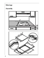
Drawers may not be fitted underneath the hob.
•
The installation must guarantee shock protection.
•
The kitchen unit in which the appliance is fitted must satisfy the sta-
bility requirements of DIN 68930.
•
For protection against moisture, all cut surfaces are to be sealed with
a suitable sealant.
•
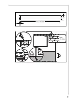
On tiled work surfaces, the joints in the area where the hob sits must
be completely filled with grout.
•
On natural, artificial stone, or ceramic tops, the snap action springs
must be bonded in place with a suitable artificial resin or mixed ad-
hesive.
•
Ensure that the seal is correctly seated in the frame and that it is
seated against the work surface without leaving any gaps. Additional
silicon sealant must not be applied; this will make removal more dif-
ficult when servicing.
•
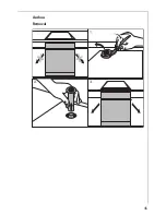
The hob must be pressed out from below when removed.
•
Clean the edge of the cut-out groove.
•
Fit the single sided adhesive strip, supplied with the hob, onto the
cut-out groove. The joining point of the two ends should be in the
middle of one of the sides of the cut-out. After cutting the correct
length (allow a few millimetres) simply press the two ends against
each other.


