background image

H

I 8820

CHDI 8820

Dunstabzugshaube

Afzuigkap

Hotte

Cooker Hood

Montage- und Gebrauchsanweisung

Installatie- en gebruiksaanwijzing

Notice d’utilisation et d’installation

Operating and Installation Instructions

Summary of Contents for CHDI 8820

Page 1: ...I 8820 CHDI 8820 Dunstabzugshaube Afzuigkap Hotte Cooker Hood Montage undGebrauchsanweisung Installatie engebruiksaanwijzing Notice d utilisation et d installation Operating and Installation Instructions ...

Page 2: ... filters 66 Grease filter LED D 66 Charcoal filter LED E 66 Resettingthesaturationindicator 66 Maintenance and care 67 Cleaning the hood 67 Metalgreasefilter 67 Removingthemetalgreasefilter 67 Charcoalfilter 68 Changing the light bulb 69 What to do if 70 Special accessories 70 Technical assistance service 71 Technical Specifications 72 Mountingaccessoriesincluded 72 Electrical connection 73 Safety...

Page 3: ...ce the filter at the recommended intervals Failure to do so could cause grease deposits to build up resulting in a fire hazard The appliance is not intended for use by young children or infirm persons without supervision Young children should be supervised to ensure that they do not play with the appliance WARNING Ensure that the appliance is switched off before replacing the lamp to avoid the pos...

Page 4: ...rom outside using a suitable ventilation hole approximately 500 600 cm2 large to avoid the possibility of a depression being created during operation of the hood If you have any doubts contact the relevant controlling authority or building inspector s office Since the rule for rooms with fuel burning appliances is outlet hole of the same size as the ventilation hole a hole of 500 600 cm2 which is ...

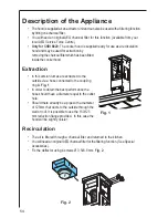
Page 5: ... In this version fumes are extracted to the outside via a hose connected to the coupling ring A Fig 1 In order to obtain the best performance the hose should have a diameter equal to the outlet hole Should there already be a pipe with a diameter of 125mm that ducts to the outside through the wall or roof it is possible to use the 150 125 mm reduction flange provided In this case the hood will be s...

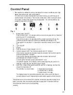
Page 6: ...n off The Intensive speed runs for 5 minutes If the hood is on when the Intensive speed is activated the hood will revert to previous speed after 5 minutes If the hood is off when the Intensive speed is activated the hood will automatically turn off after 5 minutes To interrupt the Intensive speed press button 1 or 4 The letter P appears on the display and the remaining time the point a is flashin...

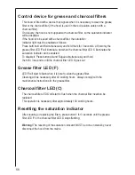
Page 7: ...indicator will be enabled To disable it Press buttons 4 and 5 again simultaneously and hold them for 3 seconds until the charcoal filter LED C goes out Grease filter LED F LED F will start to flash when it is time to clean the grease filter Cleaning will be necessary after 40 working hours Always comply with the maintenance instructions for the grease filter Charcoal filter LED C The charcoal filt...

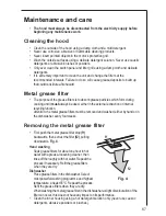
Page 8: ...ring cooking and it must always be used either in the external extraction or internal recyclingfunction Attention the metal grease filters must be removed and washed either by hand or in the dishwasher every four weeks Removing the metal grease filter First push the metal grease filter stop f1 backwards then extract the filter f2 pulling downwards Fig 4 Hand washing Soak grease filters for about o...

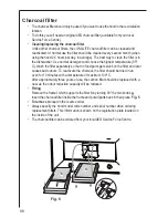
Page 9: ...eparately so that no food parts gets stuck on the filter and later causes bad odours To reactivate the charcoal the filter should be dried in an oven for 10 minutes with a temperature of maximum 100º C After approximately three years of use the carbon filter should be replaced with a new as the odour reduction capacity will be reduced Fitting Remove the frame i which supports the filter h by turni...

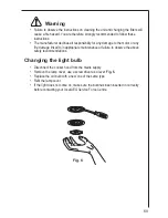
Page 10: ...or or any fire damage linked to inappropriate maintenance or failure to observe the above safety recommendations Changing the light bulb Disconnect the cooker hood from the mains supply Remove the lamp cover use a screw driver as a lever Fig 6 Replace the old bulb with a new one of the same type Refit the lamp cover If the light does not come on make sure the bulb has been inserted in correctly be...

Page 11: ...g and outlets are not blocked The cooker hood has The safety cut out device has been switched off during operation tripped Turn off the hob and then wait for the device to reset If the hood has been installed below the heights indicated in the installation instructions the motor will cut out frequently which will damage the hood If after all these checks the problem persists contact your local Ser...

Page 12: ...rce Centre and further information about Service Force please visit the website at www serviceforce co uk Please ensure that you have read the section What to do if as the engineer will make a charge if the fault is not a mechanical or electrical breakdown even the appliance is under warranty Please note that proof of purchase is required for in guarantee service calls Help us to help you Please d...

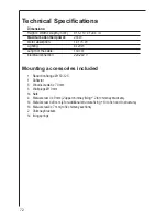
Page 13: ... Electricalconnection 220 240 V Mounting accessories included 1 Reduction flange Ø 150 125 1 Deflector 6 Wood screws 6 x 70 mm 6 WallplugsØ10mm 14 Nuts 4 Metal screw 3 x 9 mm 2 upper chimney fixing 2 for chimney brackets 14 Metal screw 4 x 8 mm 4 for additional structure fixing 10 to fix hood to structure 14 Metal screw 4 x 7 mm to fix chimeny sections 2 Chimneybrackets 14 fixingsprings ...

Page 14: ...Fixed connection of the appliance must only be carried out by an authorised electrician Electrical connection for UK only Safety warnings for the electrician Connect the hood to the mains supply via a double pole switch which has 3 mm minimum separation between the contacts The switch must be accessible at all times The following is valid in the United Kingdom only the wire which is coloured green...

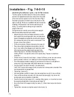
Page 15: ...the centre of the hob top and the edges must be parallel to the sides of the hob top the side of the diagram with the wording FRONT corresponds to the control panel side Prepare the electrical connection Drill as shown 6 holes for 6 wall plugs 4 plugs for fixture screw the outer screws leaving a space of about 1 cm between the screw head and the ceiling 4 Fit an exhaust pipe inside the support 5 a...

Page 16: ...75 Fig 8 2a 3 4 4 4 4 4 4 6 6 7 7 7 7 8 8 2a 5 7 9 10 10 10 10 11 11 14 5 273 273 244 214 190 6 12 2b 2b ...

Page 17: ...o sections springs must be fixed horizontally Fix the top flue assembly to the support near the ceiling with two screws 16 one each side Carry out electrical connection of control panel and bulbs 17 Join the two bottom sections of the flue covering the support 18 using 6 screws and springs 3 each side see the plan diagram for joining the two sections springs must be fixed horizontally Insert the b...

Page 18: ...77 Fig 9 15b 15b 15b 15b 15b 16 16 15b 15b 13F F 13A 15b 14 15a 15b ...

Page 19: ...78 Fig 10 18 18 18 18 18 18 18 18 18 18 M 19 19 X X 20 20 17 ...

Page 20: ...79 ...

Page 21: ...rld s No 1 choice The Electrolux Group is the world s largest producer of powered appliances for kitchen cleaning and outdoor use More than 55 million Electrolux Group products such as refrigerators cookers washing machines vacuum cleaners chain saws and lawn mowers are sold each year to a value of approx USD 14 billion in more than 150 countries around the world ...

Reviews: