67
Montage
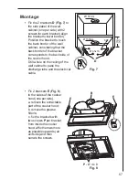
Fix the 2 brackets
D
(
Fig. 7
) to
the side panel of the wall
cabinet (one per side) with 2
screws for each bracket (align
the bracket to lower border).
Position the bracket to touch
the back border of the wall
cabinet, considering that the
back border of the bracket
corresponds to the back side of
the cooker hood;
Drill a hole on the ceiling of the
wall cabinet to pass the
discharge tube and the electrical
cable.
Fix 2 brackets
E
(
Fig. 8
)
to the sides of the cooker
hood (one per side).
a. remove the extractable
part of the cooker hood;
b. remove the grease
filter/s;
c. fix the brackets with
two screws
P
per bracket
from inside the cooker
hood, affix them as more
as possible upwards (air
exit side) and then
serrate the screws.
Ø 150mm
Ø 150mm
D
min.
135
87
Ø 4,5x16
B
E
E
P
- Ø 4 x 8
Fig. 7
Fig. 8
Summary of Contents for DF 4160
Page 19: ...71 ...

