background image

73

Grease and charcoal filter maintenance

indicator

This hood is fitted with a device that indicates when it is necessary to

clean the grease filter or the charcoal filter (if the hood is used in the

recirculation version with a charcoal filter).

On delivery, the hood is not supplied with a charcoal filter, so the

saturation indicator will be disabled.

If the hood is to be used with a charcoal filter, the saturation

indicator light must be enabled as follows:

Set the hood in “Stand by”.

Press buttons 

3

 and 

4

 simultaneously and hold them for 3 seconds.  At

first only the grease filter LED 

5

 will light up, but when the charcoal

filter LED 

6

 lights up the saturation indicator will be enabled.

To disable it: Press buttons 

3

 and 

4

 again simultaneously and hold

them for 3 seconds, until the charcoal filter LED 

6

 goes out.

Grease filter LED (5)

LED 

5

 will start to flash when it is time to clean the grease filter.

Cleaning will be necessary after 40 working hours.  Always comply

with the maintenance instructions for the grease filter.

Charcoal filter LED (6)

The charcoal filter LED 

6

 will start to flash when the charcoal filter

needs to be replaced.

This operation is necessary after approximately 160 working hours.

Resetting the saturation indicator

After cleaning or replacing the filters, press button 

2

 for 3 seconds until

the grease filter LED 

5

 or the charcoal filter LED 

6

 stops flashing.

All manuals and user guides at all-guides.com

Summary of Contents for DI 9610

Page 1: ...ap Hotte Cooker Hood Montage und Gebrauchsanweisung Installatie en gebruiksaanwijzing Notice d utilisation et d installation Operating and Installation Instructions All manuals and user guides at all guides com a l l g u i d e s c o m ...

Page 2: ...maintenance indicator 72 Maintenance and Care 73 Cleaning the hood 73 Metal grease filter 73 Removing the front panels 73 Charcoal filter 75 Changing the light bulb 76 Technical assistance service 77 Technical Details 78 Mounting accessories included 78 What to do if 79 Special accessories 79 Electrical connection 81 Wall unit mounting 84 All manuals and user guides at all guides com ...

Page 3: ...ung children or infirm persons without supervision Older children must be supervised if using the appliance Young children should be supervised to ensure that they do not play with the appliance WARNING Ensure that the appliance is switched off before replacing the lamp to avoid the possibility of electric shock This appliance is marked according to the European directive 2002 96 EC on Waste Elect...

Page 4: ...e relevant local authorities When the unit is used in extraction mode a sufficiently large ventilation hole must be provided with dimensions that are approxi mately the same as the outlet hole National and regional building regulations impose a number of restrictions on using hoods and fuel burning appliances connected to a chimney such as coal or oil room heaters and gas fires in the same room Ho...

Page 5: ...lways follow a gentle curve keep the hose as large as possible preferably the same diameter as the outlet hole the length should be no more than 3 metres with one 90 bend 2 metres with two 90 bends Bends of more than 90 will reduce the efficiency of the hood and reduce the airflow Failure to observe these basic instructions will drastically reduce the performance and increase the noise levels of t...

Page 6: ... via a hose connected to the coupling ring A Fig 1 In order to obtain the best performance the hose should have a diameter equal to the outlet hole Should there already be a pipe of diameter 125 or 120 mm that ducts to the outside through the walls it is possible to use the 150 125 120 mm reduction flange provided In this case the hood will be slightly noisier Recirculation mode The air is filtere...

Page 7: ... to increase the luminosity of the lights press again to turn off the lights 2 Motor OFF and reset filter saturation indicators key 3 Cyclical 1 2 3 speed selection key 4 Intensive speed selection key lasts 5 minutes after which the hood returns to the previously set speed 5 Led speed suction 1 indicator power and grease filter saturation indicator n this case the led flashes 6 Led speed suction 2...

Page 8: ... charcoal filter LED 6 lights up the saturation indicator will be enabled To disable it Press buttons 3 and 4 again simultaneously and hold them for 3 seconds until the charcoal filter LED 6 goes out Grease filter LED 5 LED 5 will start to flash when it is time to clean the grease filter Cleaning will be necessary after 40 working hours Always comply with the maintenance instructions for the greas...

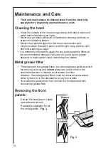
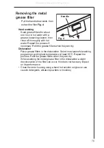
Page 9: ...e the filters at the recommended intervals Failure to do so will cause grease deposits to build up that could constitute a fire hazard Metal grease filter The purpose of the grease filters is to absorb grease particles which form during cooking and it must always be used either in the external extraction or internal re circulation function Attention the metal grease filters must be removed and was...

Page 10: ...hwasher Place grease filters in the dishwasher Select most powerful washing programme and highest temperature at least 65 C Repeat the process Refit the grease filters when they are dry When washing the metal grease filter in the dishwasher a slight discolouration of the filter can occur this does not have any impact on its performance Clean the inner housing using a hand hot solution only never u...

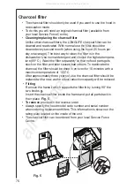
Page 11: ...he filter and later causes bad odours To reactivate the charcoal the filter should be dried in an oven for 10 minutes with a maximum temperature of 100º C After approximately three years of use the charcoal filter should be replaced with a new as the odour reduction capacity will be reduced Fitting Remove the frame i which supports the filter h by turning 90 the two knobs g Insert the charcoal fil...

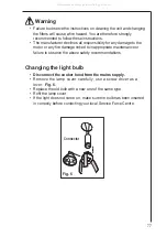
Page 12: ... inappropriate maintenance or failure to observe the above safety recommendations Changing the light bulb Disconnect the cooker hood from the mains supply Remove the lamp cover carefully use a screw driver as a lever Fig 6 Replace the old bulb with a new one of the same type Refit the lamp cover If the light does not come on make sure the bulb has been inserted in correctly before contacting your ...

Page 13: ...e area For the address of your local Service Force Centre and further information about Service Force please visit the website at www serviceforce co uk Please ensure that you have read the section What to do if as the engineer will make a charge if the fault is not a mechanical or electrical breakdown even the appliance is under warranty Please note that proof of purchase is required for in guara...

Page 14: ... Maximum absorbed power 255 W Motor absorption 175 W Lighting 4 x 20 W 30 Ø35 12V GU4 Length of the cable 150 cm Electrical connection 220 240 V Fuse rating 5A 250V Attention To guarantee the same quality of illumination we advise using the same type of light Halogen Lamp PHILIPS STANDARD LINE Code 425409 20W 30 Ø35 12V GU4 Mounting accessories included 1 Reduction flange Ø 150 125 1 Deflector 6 s...

Page 15: ...The cooker hood has The safety cut out device has been switched off tripped during operation Turn off the hob and then wait for the device to reset If the hood has been installed below the heights indicated in the installation instructions the motor will cut out frequently which will damage the hood If after all these checks the problem persists contact your local Service Force Centre quoting the ...

Page 16: ...ust only be carried out by an authorised electrician Electrical connection for UK only Safety warnings for the electrician Connect the hood to the mains supply via a double pole switch which has 3 mm minimum separation between the contacts The switch must be accessible at all times The following is valid in the United Kingdom only the wire which is coloured green and yellow must be connected to th...

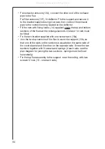
Page 17: ...re of the diagram must match the centre of the hob top and the edges must be parallel to the sides of the hob top Prepare the electrical connection Drill as shown 6 holes for 6 wall plugs 4 plugs for fixture screw the outer screws leaving a space of about 1 cm between the screw head and the ceiling 4 Fit an exhaust pipe inside the support 5 and connect it to the motor compartment connection ring e...

Page 18: ...83 2a 3 4 4 4 4 4 4 6 6 7 7 7 7 8 8 2a 5 7 9 10a 14 5 273 273 244 214 190 6 12 2b 2b 11a 11a 11b 11b 10a 10a 10a 10a 10a 10a 10a Fig 8 FRONT All manuals and user guides at all guides com ...

Page 19: ... slots A total of 14 nuts must be fitted Fix the two bracket supplied with one screw each 15a Join the two top sections of the flue to cover the support 15b so that one of the slots on the sections is situated on the same side of the control panel and the other on the opposite side Screw the two sections together with 8 screws and springs 4 each side see the plan diagram for joining the two sectio...

Page 20: ...85 15 15 15 15 15 16 16 15 15 13F F 13A 15 14 15 Fig 9 All manuals and user guides at all guides com ...

Page 21: ...om sections of the flue covering the support 18 using 6 screws and springs 3 each side see the plan diagram for joining the two sections springs must be fixed horizontally Fig 10 18 18 18 18 18 18 18 18 18 18 M 18 All manuals and user guides at all guides com a l l g u i d e s c o m ...

Page 22: ...he 2 tabs 19 supplied to cover the fixing points of the bottom flue CAUTION THE BOTTOM FLUE TABS ARE THE NARROWER AND SHALLOWER ONES Remount the front panels and the greases filter Turn the mains power on again at the central electrical panel and check for correct hood operation X 19 19 X Fig 11 All manuals and user guides at all guides com ...

Page 23: ...oducer of powered appliances for kitchen cleaning and outdoor use More than 55 million Electrolux Group products such as refrigerators cookers washing machines vacuum cleaners chain saws and lawn mowers are sold each year to a value of approx USD 14 billion in more than 150 countries around the world AEG 55 77 High Street SLOUGH Berks SL1 1DZ http www aeg co uk All manuals and user guides at all g...

Reviews: